Introduction
The manufacturing of TPR thermoplastic rubber based masterbatch incorporating CaCO3 calcium carbonate filler represents a specialized segment of polymer compounding that demands precise control over multiple processing parameters. This masterbatch combines the elastic properties of TPR with the cost-effectiveness and performance enhancement provided by calcium carbonate, creating a versatile additive system for downstream compounding operations. The twin screw extruder has emerged as the indispensable processing equipment for this application due to its superior mixing efficiency and ability to maintain consistent processing conditions.
The chemical composition of TPR materials distinguishes them from other elastomeric systems. TPR primarily consists of styrenic block copolymers with SBS styrene-butadiene-styrene and SEBS styrene-ethylene-butylene-styrene being the most common types. These materials exhibit unique viscoelastic behavior that requires specialized processing approaches. The incorporation of CaCO3 filler must be accomplished without compromising the elastic recovery and flexibility characteristics that make TPR valuable in applications such as automotive components, footwear, consumer goods, and industrial products.
Calcium carbonate serves multiple critical functions in TPR CaCO3 masterbatch formulations. Beyond the obvious economic benefit of polymer displacement, calcium carbonate can enhance dimensional stability, improve processing characteristics, modify surface properties, and provide specific mechanical property modifications. The interaction between the rigid inorganic filler particles and the elastomeric polymer matrix determines the final product characteristics. Particle size distribution, surface treatment, and filler loading level all influence processing behavior and end-use performance.
The global demand for TPR CaCO3 masterbatch continues to expand across multiple industries. This growth stems from increasing cost pressures on manufacturers combined with sustainability initiatives that promote the use of mineral-filled systems. Masterbatch producers must balance economic objectives with performance requirements, delivering products that meet stringent quality standards while maintaining competitive pricing. Success in this market requires deep understanding of material science, processing technology, and specific application requirements.
Formulation Ratios (Different Types)
Standard TPR CaCO3 Masterbatch
The standard formulation for TPR CaCO3 masterbatch typically comprises 54% calcium carbonate filler, 40% TPR carrier resin, and 6% processing aids and dispersants. This composition provides an effective balance between cost reduction and maintenance of elastomeric properties. The TPR carrier must be carefully selected based on the specific styrenic block copolymer type used in the target base polymer. SEBS-based TPR is commonly used for applications requiring superior weatherability and thermal stability, while SBS-based TPR offers excellent tensile strength and abrasion resistance.
Calcium carbonate grade selection is critical for achieving desired product characteristics. Ground calcium carbonate with particle sizes ranging from 1.2 to 3.5 microns provides good dispersion and reinforcement potential. Surface-treated grades with stearic acid coating demonstrate improved compatibility with TPR polymers compared to untreated grades. The formulation may incorporate processing aids such as internal lubricants or slip agents to improve flow characteristics during subsequent processing of the masterbatch into final compounds.
Maximum Loading Formulation
Maximum loading TPR CaCO3 masterbatch formulations are designed for applications where cost reduction is the primary objective and some property reduction is acceptable. These formulations typically contain 72-76% calcium carbonate, 22-26% TPR carrier resin, and 2% dispersing agents. The extremely high filler content significantly reduces material costs but presents substantial processing challenges that must be addressed through specialized formulation design and process optimization.
The maximum filler loading dramatically increases melt viscosity and alters the rheological behavior of the compound. This necessitates the use of specialized calcium carbonate grades with very fine particle size below 2 microns and effective surface treatment to maintain acceptable flow properties. Dispersing agents are particularly important in these formulations to prevent filler agglomeration and maintain homogeneous distribution throughout the TPR matrix. Processing temperatures typically require 5-10°C increase compared to standard formulations to overcome the increased viscosity.
Premium Performance Formulation
Premium performance TPR CaCO3 masterbatch formulations are designed for applications demanding superior mechanical properties and enhanced processing characteristics. These formulations typically contain 42% calcium carbonate, 52% TPR carrier resin, and 6% coupling agents and performance additives. The increased polymer content provides better stress transfer between filler particles and the elastomeric matrix, maintaining tensile strength and elongation properties even with significant filler loading.
Coupling agents such as maleic anhydride grafted polymers improve interfacial adhesion between CaCO3 particles and the TPR matrix. These chemically active agents form bonds between the inorganic filler surface and organic polymer chains, preventing particle pull-out and maintaining elastic recovery characteristics. The additional cost of coupling agents is justified in applications where mechanical performance is critical, such as automotive interior components or industrial seals requiring long-term durability.
Enhanced Weatherability Formulation
Enhanced weatherability TPR CaCO3 masterbatch formulations incorporate ultraviolet stabilizers and antioxidants to prevent degradation from environmental exposure in outdoor applications. These formulations typically contain 48% calcium carbonate, 46% TPR carrier resin, 4% UV stabilizers and antioxidants, and 2% dispersants. The stabilizers may include hindered amine light stabilizers HALS, ultraviolet absorbers UVAs, and phenolic antioxidants depending on the specific degradation resistance requirements.
The incorporation of stabilizers requires careful attention to thermal stability during processing, as some stabilizers may degrade at typical TPR processing temperatures. Formulation development must balance weather protection requirements with processing constraints. The calcium carbonate loading may be adjusted slightly to accommodate the stabilizer package while maintaining desired product characteristics. Testing under accelerated weathering conditions is essential to verify protection effectiveness before commercial production.
Slip Agent Enhanced Formulation
Slip agent enhanced TPR CaCO3 masterbatch formulations incorporate slip additives to reduce coefficient of friction and improve surface properties. These formulations typically contain 50% calcium carbonate, 46% TPR carrier resin, 3% slip agents, and 1% dispersants. The slip agents, typically fatty acid amides or erucamide, migrate to the surface over time, providing a lubricating layer that reduces friction.
The selection of slip agents must consider compatibility with the TPR matrix and processing temperature constraints. Slip agents may affect other properties such as surface appearance or printing characteristics, requiring formulation optimization. The slip effect may develop over time as the additive migrates to the surface. Formulation testing should verify slip performance under the expected service conditions of the final product. Different slip agents offer varying effectiveness depending on the TPR type and application requirements.
Production Process
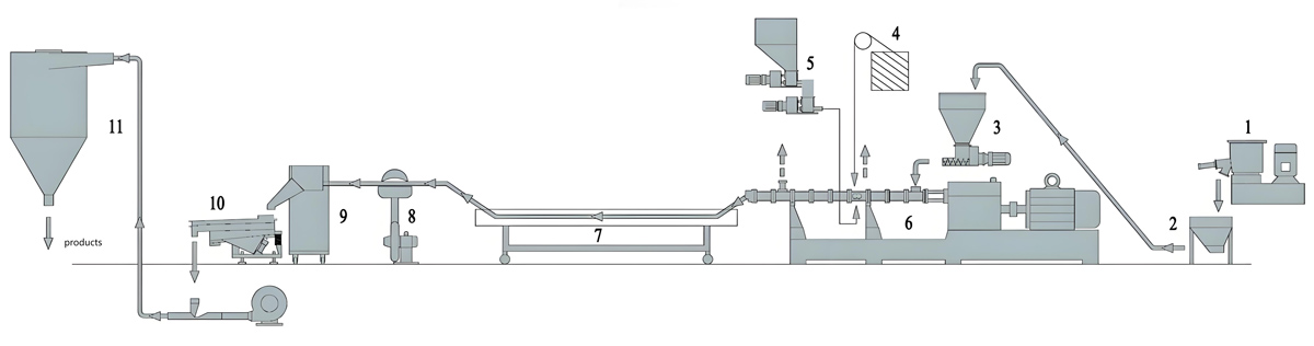
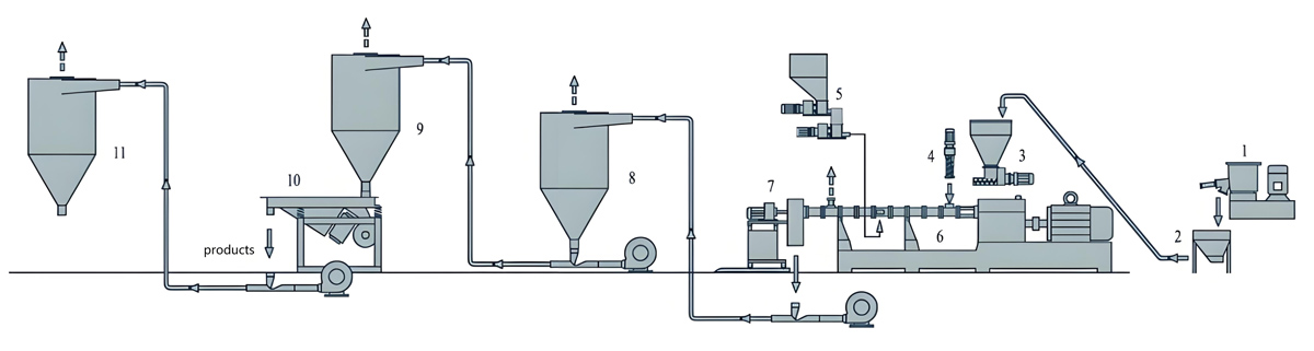
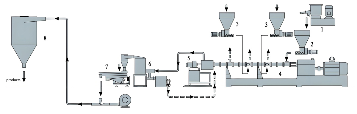
The production of TPR CaCO3 filled masterbatch follows a comprehensive process that transforms raw materials into a homogeneous, uniformly dispersed finished product. Each stage of the process requires careful control and monitoring to ensure consistent quality and efficient operation. The twin screw extruder provides the core processing capability, but successful production depends on properly prepared materials, optimized processing conditions, and effective quality control throughout the production sequence.
Raw Material Quality Control
Raw material quality control begins with proper inspection and documentation of incoming materials. Calcium carbonate, TPR carrier resin, and additives should be verified against purchase specifications for identity, appearance, particle size distribution, and certificate of analysis data. Moisture content analysis is particularly important, though TPR is generally less hygroscopic than some other elastomers. Each material should be assigned a unique lot number and stored in appropriate conditions to prevent contamination and property changes.
Sampling protocols should be established to ensure representative testing of incoming materials. Calcium carbonate samples should be analyzed for particle size distribution, surface treatment content, moisture content, and whiteness index. TPR resin samples should be evaluated for melt flow index, molecular weight distribution, and thermal stability. Additive samples should be verified for chemical identity and purity. Rejected materials should be clearly identified and segregated to prevent accidental use in production.
Material Storage and Handling
Storage conditions maintain material quality until use. Calcium carbonate should be stored in dry environments with controlled humidity to prevent caking and reduce drying requirements. Bulk storage silos should be equipped with moisture barriers and appropriate ventilation. Bagged calcium carbonate should be stored on pallets away from direct contact with floors that could transfer moisture. TPR resins, while less sensitive to moisture than some polymers, still benefit from storage away from direct sunlight and at controlled temperatures below 30°C.
Material handling systems should minimize contamination and material degradation. Pneumatic conveying systems for calcium carbonate should use dry air to prevent moisture pickup. TPR resin handling should minimize static electricity generation and material attrition. First-in, first-out inventory management ensures proper material rotation and prevents extended storage that could lead to property changes. Material segregation prevents cross-contamination between different grades or colors.
Drying Operations
Material drying removes moisture that could cause voids, surface defects, or processing problems during extrusion. While TPR is generally less hygroscopic than some elastomers, calcium carbonate can adsorb moisture from ambient air that affects processing quality. Typical drying temperatures range from 95-105°C for TPR resins and 105-115°C for calcium carbonate. Drying time varies from 2-4 hours depending on material quantity, dryer capacity, and initial moisture content.
Desiccant dryers provide the most effective moisture removal by using dehumidified air with very low dew points below -20°C. The air flow must be sufficient to carry moisture away from the material bed and ensure uniform drying throughout the material mass. Over-drying should be avoided as it can cause thermal degradation of sensitive additives or oxidation of TPR components. Moisture analysis before and after drying confirms the effectiveness of the drying process and establishes the optimal drying parameters.
Weighing and Dosing
Accurate weighing and dosing of components ensures consistent formulation ratios from batch to batch. Automated weighing systems with gravimetric accuracy of 0.1% or better are preferred for consistent quality. Manual weighing may be acceptable for small batch production but introduces human error potential and labor inefficiency. The weighing system should be calibrated regularly according to established schedules using certified weights.
Weighing accuracy becomes increasingly important as component quantities decrease, particularly for additives that may be added at very low percentages. Tare weight of containers should be accounted for to prevent systematic errors. Weighing records should be maintained for traceability and quality control purposes. For multi-component formulations, individual component weighing allows precise ratio control and adjustment flexibility without requiring new premixes.
Premixing and Homogenization
Premixing combines the various solid components into a homogeneous blend before introduction to the extruder. This step reduces the mixing burden on the extruder and improves process stability. High-speed mixers with capacities from 100 to 1000 liters provide efficient blending of pellets, powders, and additives. Mixing times typically range from 3 to 5 minutes at 900-1600 rpm depending on mixer design and formulation characteristics.
The premixing process generates heat through friction that must be controlled to prevent material softening or degradation. Temperature monitoring during mixing prevents excessive heat buildup that could cause TPR pellets to become tacky and agglomerate. Maximum mixing temperatures should be maintained below 75°C to preserve free-flowing characteristics. Some mixers incorporate water cooling jackets or controlled air circulation to manage temperature rise during extended mixing cycles. Mixer cleaning procedures prevent cross-contamination between different formulations.
Extruder Feeding
The extruder feeding system delivers the premixed material to the processing section at a controlled rate that matches processing requirements. Gravimetric feeders provide the highest accuracy by continuously weighing the material stream and automatically adjusting feeder speed to maintain target throughput. For TPR CaCO3 masterbatch, feed rates typically range from 100 to 500 kg/h depending on extruder size and formulation. Feeder hopper design should prevent material bridging and ensure consistent flow.
Feeder calibration should be performed regularly to maintain accuracy within 1% of setpoint. Calibration involves running material through the feeder for a timed interval, weighing the delivered material, and comparing to the setpoint. Adjustments are made as needed to correct any deviations. Feed throat design should incorporate smooth transitions to prevent material hang-up. Some systems use force feed screws or crammers to ensure consistent material entry, particularly for formulations with high bulk density or poor flow characteristics.
Melting and Compounding
The melting and compounding process transforms the premixed materials into a homogeneous melt with uniformly dispersed calcium carbonate particles. The process begins in the feed section of the extruder where conveying elements transport solid material forward. Progressive heating in subsequent barrel sections melts the TPR matrix, creating a melt that can be mixed with the calcium carbonate filler. The intermeshing screws generate shear forces that disperse the filler throughout the melt.
Barrel temperature profile increases gradually from feed to die to accommodate melting and mixing requirements. Typical profiles start at 155-165°C in the feed zone, increase to 185-205°C in the melting zone, and reach 205-225°C in the mixing zone. The precise temperatures depend on the specific TPR type, with SEBS generally requiring slightly higher temperatures than SBS-based formulations. Temperature uniformity across the barrel width is essential for consistent processing quality and product uniformity.
Filler Dispersion
Filler dispersion is a critical process that determines product quality and performance. The screw configuration must provide sufficient distributive and dispersive mixing to break up calcium carbonate agglomerates and achieve uniform distribution throughout the TPR matrix. Kneading blocks in the mixing zones provide dispersive mixing through high shear action that separates individual particles. Conveying elements with mixing sections provide distributive mixing that ensures uniform spatial distribution.
The degree of mixing required depends on the calcium carbonate particle size and loading. Finer particles and higher loadings require more intensive mixing. However, excessive mixing can generate too much shear heat, risking thermal degradation of the TPR. The optimal mixing intensity balances dispersion quality with thermal considerations. Residence time in the mixing zone should be sufficient to achieve complete dispersion without extending exposure to high temperatures unnecessarily.
Ventilation and Degassing
Ventilation and degassing remove volatiles, moisture, and entrapped air from the melt. This step is particularly important when using materials that may release volatiles during processing or when the formulation includes additives with decomposition temperatures close to the processing temperature. A vent zone located after the mixing section provides atmospheric or vacuum conditions that allow volatiles to escape from the melt.
Vent port sizing must prevent melt leakage while providing adequate surface area for volatile removal. Vent depth typically ranges from 6-18mm depending on the melt viscosity and vacuum level. Vacuum levels for TPR CaCO3 masterbatch typically range from 480-680 mbar absolute pressure. Vacuum pump capacity must be sufficient to maintain the required vacuum level while accounting for air leakage through the screw vent flights and around the vent port. Vent port cleaning prevents material buildup that could reduce effectiveness.
Die Extrusion and Strand Formation
The die shapes the homogeneous melt into multiple strands for subsequent cooling and pelletizing. Die design significantly affects strand quality and downstream processing efficiency. For TPR CaCO3 masterbatch, strand dies typically feature 4-8 round holes with diameters ranging from 2.2mm to 3.8mm depending on throughput requirements. Die land length should be 3.5-5.5 times the hole diameter to control die swell and ensure smooth strand formation.
Die temperature is typically set at the same level as the final barrel zone or slightly higher by 3-8°C to maintain proper melt viscosity for smooth strand formation. Die heating must be uniform across all holes to ensure consistent strand dimensions. Die material selection considers wear resistance from abrasive calcium carbonate filler. Hardened tool steel dies provide extended service life. Die surfaces should be polished to minimize material build-up and facilitate clean strand separation. Die lip design affects strand quality and should prevent sagging or deformation.
Strand Cooling and Solidification
Strand cooling solidifies the extruded strands to temperatures suitable for pelletizing. Water bath cooling is the most common method, offering rapid heat transfer and good temperature control. Water temperature is maintained between 12-22°C for optimal quenching of TPR materials. The bath length provides sufficient residence time for complete cooling, typically requiring 3.5-6.5 meters of water contact depending on line speed and strand diameter.
Water circulation ensures uniform cooling across all strands. Agitation or spray nozzles may be used to enhance heat transfer and prevent temperature stratification in the bath. Some facilities use multiple cooling tanks at different temperatures to implement controlled cooling profiles that optimize product properties. The cooling system must be designed to handle the thermal load from the extrusion process while maintaining stable water temperature. Water filtration removes debris that could affect cooling efficiency or contaminate strands.
Pelletizing and Finishing
Pelletizing converts the cooled strands into uniform pellets suitable for downstream processing. Strand pelletizers with rotary cutting knives are commonly used for TPR masterbatch applications. The cutting speed is synchronized with strand line speed to maintain consistent pellet length, typically 2.2-3.8mm. Knife sharpness and proper alignment are critical for clean cuts without generating fines or causing strand deformation. Knife material selection considers wear resistance from abrasive calcium carbonate.
Pellet quality inspection includes checks for size consistency, shape uniformity, and absence of defects. Pellets should be free of voids, surface irregularities, or color inconsistencies. Automatic pelletizing systems may include optical sorting to reject defective pellets. Proper pellet handling and packaging prevent moisture absorption and contamination during storage and transportation. Final product testing confirms that all specifications are met before shipment to customers.
Production Equipment Introduction
Equipment selection for TPR CaCO3 masterbatch production significantly influences product quality, production efficiency, and operational costs. The twin screw extruder serves as the core processing equipment, but supporting systems for material handling, temperature control, strand formation, cooling, and pelletizing are equally important. Each component must be properly specified, integrated, and maintained to achieve optimal performance.
Twin Screw Extruder System
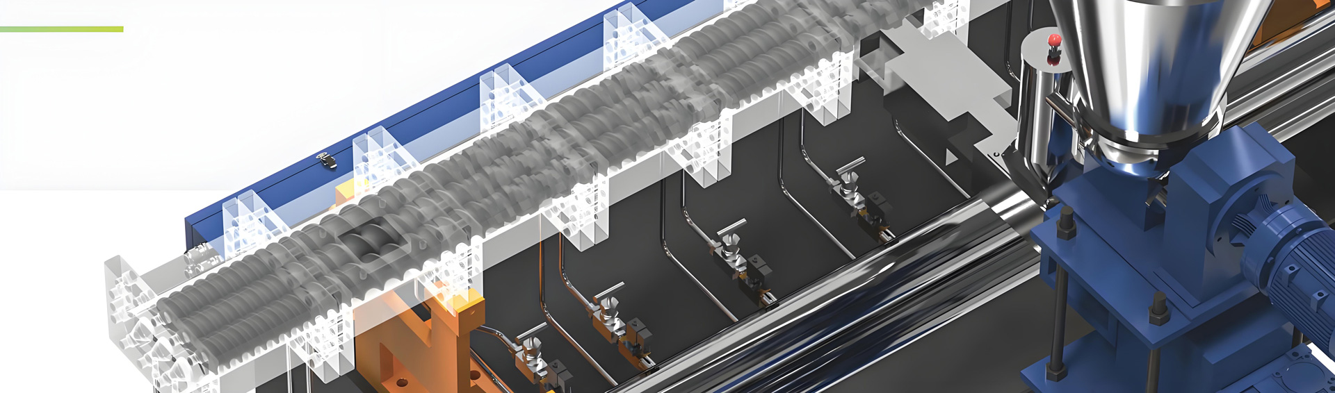
The twin screw extruder provides the primary processing capability for TPR CaCO3 masterbatch production. Co-rotating intermeshing extruders are preferred for this application due to their positive displacement characteristics and superior mixing performance. The KTE Series twin screw extruders offer excellent performance for this application, featuring robust construction designed for continuous operation with abrasive fillers. Screw diameters range from 40mm to 130mm, providing throughput capacities from 50 kg/h to over 2000 kg/h.
The extruder design includes modular barrel construction with individually controlled heating zones. This arrangement enables precise thermal profiling tailored to specific TPR types and formulations. Heavy-duty gearboxes deliver the high torque required for processing high-viscosity melts with high filler loading. Drive systems provide stable speed control across the operating range, typically from 50 to 500 rpm depending on extruder size. Control systems with touchscreen interfaces facilitate process monitoring and adjustment.
Screw Elements and Configuration
Screw configuration determines the mixing performance and product quality. Standard configurations for TPR CaCO3 masterbatch include conveying elements in the feed section for efficient solids transport. Kneading blocks in the melting and mixing zones provide dispersive mixing to break up filler agglomerates. Conveying elements with mixing sections in the final homogenization zone ensure uniform melt delivery to the die.
The specific arrangement of screw elements should be optimized for formulation characteristics. Higher filler loadings generally require more aggressive mixing elements. Kneading block stagger angles of 35-65 degrees provide effective dispersive mixing. Some configurations incorporate reverse elements to increase residence time and mixing intensity. The flexibility to modify screw configurations allows optimization for different formulations without requiring equipment replacement. Proper screw design ensures efficient solids conveying, complete melting, uniform filler dispersion, and consistent melt delivery.
Barrel Design Features
Barrel design provides the housing for the rotating screws and the thermal control needed for processing. Bimetallic barrel liners with wear-resistant alloys are essential for TPR CaCO3 masterbatch production due to the abrasive nature of the filler. Electric heating bands with individual zone control enable precise temperature management along the barrel length. Temperature sensors at each zone provide feedback for closed-loop temperature regulation.
Some barrel sections may incorporate water cooling channels to remove excess shear heat and maintain temperature stability. This is particularly important in high-viscosity formulations where shear heating can be significant. The barrel must be properly supported and aligned to prevent binding between the barrel and screws. Barrel sections are typically flanged together with precision alignment features. Regular inspection identifies wear patterns and determines the need for barrel relining or replacement.
Feeding Equipment Options
Feeding equipment ensures consistent material delivery to the extruder. Gravimetric feeders provide the highest accuracy and are strongly recommended for masterbatch production. These systems continuously weigh the material stream and automatically adjust feeder speed to maintain target throughput, typically achieving accuracy within 1%. For multi-component formulations, multiple gravimetric feeders can introduce individual components at precisely controlled ratios.
Volumetric feeders offer a lower-cost alternative but provide less consistent feeding, particularly when material properties vary. Feed hopper design should prevent material bridging and ensure smooth flow. Hopper agitation systems or vibrators may be incorporated to prevent bridging. Water-cooled feed throats prevent premature melting that could cause feed instability. Feeder capacity should match production requirements to minimize refill frequency and maintain continuous operation.
Die and Strand Handling
Die systems shape the molten polymer into strands for subsequent processing. Strand dies with multiple round holes are most common for TPR masterbatch. The number and diameter of holes depend on throughput requirements and desired strand size. Die land length affects die swell and strand uniformity, with optimal land lengths typically 3.5-5.5 times the hole diameter.
Die material must resist wear from abrasive calcium carbonate. Hardened tool steel dies provide extended service life. Quick-change die designs facilitate cleaning and maintenance, reducing downtime between production runs. Die heating may be accomplished with electric band heaters or cartridge heaters. Strand handling equipment including guides, rollers, and tension controls ensure proper strand positioning and smooth transport from the die to the cooling system.
Cooling System Components
Cooling systems solidify the extruded strands to temperatures suitable for pelletizing. Water bath systems are most common, consisting of stainless steel tanks with controlled water temperature and circulation. Tank length provides sufficient residence time for complete cooling, typically 3.5-6.5 meters depending on line speed. Water temperature control between 12-22°C ensures optimal quenching of TPR materials.
Water pumps and circulation systems ensure uniform water flow and temperature throughout the bath. Filtration systems remove debris and maintain water quality. Temperature control units regulate water temperature through heating and cooling as needed. Some facilities use air knives after the water bath to remove surface water before pelletizing, preventing moisture-related quality issues. Cooling system design should consider thermal load from the extrusion process and local water quality characteristics.
Pelletizing Equipment Types
Pelletizing equipment converts cooled strands into uniform pellets. Strand pelletizers with rotary cutting knives are commonly used, offering precise control over pellet length and shape. The cutting rotor typically features 4-8 knives that cut strands against a fixed bed knife. Cutting speed synchronization with strand line speed maintains consistent pellet dimensions. Knife material selection considers wear resistance from abrasive calcium carbonate.
Underwater pelletizing systems offer an alternative for formulations sensitive to strand handling or requiring rapid quenching. These systems cut strands directly in a water bath, providing uniform cooling and preventing strand sticking. However, underwater systems are more complex and expensive than strand pelletizers. The choice between pelletizing methods depends on formulation characteristics, production volume, and quality requirements.
Control and Automation
Control systems monitor and regulate process parameters to ensure consistent operation and product quality. Modern extruders feature PLC-based controls with touchscreen interfaces providing real-time monitoring of temperature, pressure, screw speed, and feed rate. Data logging capabilities enable process analysis and traceability. Safety interlocks prevent operation under unsafe conditions.
Advanced control systems may include automated recipe management for quick changeovers between formulations. Integration with upstream and downstream equipment enables coordinated operation of the entire production line. Remote monitoring capabilities allow operators to supervise process conditions from control rooms. Statistical process control features help maintain product quality within specification limits and enable early detection of process deviations.
Parameter Settings
Process parameter optimization is essential for producing high-quality TPR CaCO3 filled masterbatch consistently. The interaction between temperature profile, screw speed, feed rate, and other variables determines product quality, production efficiency, and equipment wear. Understanding these relationships enables fine-tuning for specific formulations and equipment configurations.
Temperature Profile Configuration
The temperature profile along the extruder must accommodate the melting characteristics of the TPR carrier while preventing thermal degradation. For most TPR CaCO3 formulations, temperatures increase gradually from feed to die. Feed zone temperatures of 155-165°C ensure efficient solids conveying without premature melting. Melting zone temperatures of 185-205°C facilitate complete polymer melting. Mixing zone temperatures of 205-225°C ensure proper viscosity for mixing and dispersion.
The specific temperature profile depends on the TPR type. SEBS-based formulations typically require temperatures of 195-225°C, while SBS-based formulations process at slightly lower temperatures of 185-215°C. Calcium carbonate loading affects the optimal profile, with higher loadings requiring slightly higher temperatures to overcome increased viscosity. Temperature stability within ±2°C is essential for consistent product quality. The final zone temperature before the die may be reduced by 3-5°C to control die swell.
Screw Speed Determination
Screw speed affects residence time, shear input, and throughput. For TPR CaCO3 masterbatch, screw speeds typically range from 220 to 370 rpm. Higher speeds increase throughput but may reduce residence time and increase melt temperature through shear heating. Lower speeds provide longer residence time for improved mixing but reduce production capacity.
The relationship between screw speed and product quality depends on formulation characteristics. High filler loading formulations may require higher speeds to provide sufficient shear for dispersion. However, excessive speed can cause thermal degradation of TPR, particularly for SBS-based formulations with lower thermal stability. Monitoring melt temperature and product quality while adjusting screw speed helps identify optimal operating conditions. Speed changes should be made gradually to allow process stabilization.
Feed Rate Optimization
Feed rate determines throughput and affects the degree of fill in the extruder channels. Proper feed rate ensures the extruder operates at optimum capacity without overfilling or starving the screws. Feed rate is typically coordinated with screw speed to maintain the desired feed ratio, which ranges from 0.35 to 0.75 kg/(rpm·cm³ of screw volume) for TPR CaCO3 formulations.
Higher feed rates increase throughput but may reduce mixing quality if the extruder becomes overfilled. Lower feed rates provide better mixing but reduce production efficiency. The feed rate should be adjusted in conjunction with screw speed to maintain stable processing. Gravimetric feeders with closed-loop control help maintain consistent feed rates despite variations in material bulk density. Feed rate adjustments should be made in small increments to prevent process upsets.
Pressure Monitoring and Control
Pressure monitoring provides valuable information about process stability and product consistency. Die pressure typically ranges from 22 to 42 bar for TPR CaCO3 masterbatch. Higher pressures indicate increased viscosity, which may result from excessive filler loading, low temperatures, or material degradation. Lower pressures may indicate inadequate mixing or material property changes.
Pressure variations along the barrel provide diagnostic information about processing conditions. Increasing pressure in the feed section may indicate feeding problems. Rising pressure in the melting zone suggests incomplete melting or viscosity increase. Stable pressure in the mixing zone indicates proper mixing conditions. Pressure transducers installed at multiple barrel points enable detailed process analysis. Pressure alarms should be set to alert operators of abnormal conditions before equipment damage or product quality issues occur.
Vacuum Venting Settings
Vacuum venting removes volatiles and moisture from the melt. For TPR CaCO3 formulations with additives that may release volatiles, vent zone vacuum levels of 480-680 mbar absolute pressure are typical. The vent port should be sized appropriately to handle the expected vapor load without causing melt leakage. Vent zone temperature should be set to maintain proper melt viscosity while preventing material leakage.
Vacuum pump capacity must be sufficient to maintain the required vacuum level, accounting for air leakage through the screw vent flights. The vent zone location after the mixing section ensures that most volatiles have been released from the melt before venting. Vent port design should prevent material accumulation that could reduce effectiveness. Regular cleaning of vent ports maintains optimal performance. Vacuum level should be monitored to ensure proper operation.
Equipment Price
Capital investment in production equipment represents a significant consideration for TPR CaCO3 masterbatch manufacturers. Understanding the cost structure for different equipment components enables accurate budgeting and investment decisions. Prices vary based on capacity, features, and manufacturer, but typical ranges provide useful reference points for planning.
Twin Screw Extruder Investment
Twin screw extruders represent the largest capital expense for masterbatch production. Pricing for co-rotating twin screw extruders ranges from approximately USD 75,000 for a 40mm diameter, 50 kg/h capacity unit to USD 440,000 for a 130mm diameter, 2000 kg/h capacity system. Mid-range models with 60-80mm screw diameters and 300-600 kg/h capacities typically cost between USD 150,000 and USD 300,000.
Price variations within each size category depend on L/D ratio, gearbox capacity, control system sophistication, and additional features. Higher L/D ratios (48:1 vs. 40:1) typically add 18-28% to the base price. Advanced control systems with recipe management and data logging capabilities may add USD 18,000-35,000 to the cost. Custom screw configurations with specialized elements may incur additional charges depending on complexity.
Feeding System Costs
Feeding systems vary widely in cost depending on type and features. Gravimetric feeders for single-component feeding typically cost USD 8,000-22,000 per unit, depending on throughput capacity and accuracy requirements. Multi-component gravimetric feeding systems with integrated control may cost USD 35,000-80,000 for three to six component configurations. Volumetric feeders offer a lower-cost alternative at USD 6,000-14,000 per unit.
Material handling systems including silos, conveying systems, and receivers add USD 35,000-160,000 depending on capacity and automation level. The investment in feeding systems should be justified by the benefits of improved accuracy and reduced labor requirements. Larger facilities with multiple extrusion lines may invest USD 350,000 or more in comprehensive material handling infrastructure.
Die and Cooling Equipment
Die systems represent a moderate investment. Standard strand dies for TPR CaCO3 masterbatch typically cost USD 6,000-14,000 depending on hole configuration and materials. Quick-change die systems that facilitate rapid changeovers may cost USD 18,000-35,000. Strand handling equipment including guides, tension controls, and take-up systems adds USD 12,000-28,000 to the total investment.
Cooling systems typically cost USD 18,000-45,000 depending on length, capacity, and features. Additional cooling equipment including water pumps, filtration systems, and temperature control units add USD 10,000-25,000. Water treatment equipment for maintaining water quality and preventing algae growth costs USD 6,000-14,000.
Pelletizing Equipment
Strand pelletizers range in price from USD 22,000 for basic models to USD 55,000 for high-capacity units with advanced features. Underwater pelletizing systems represent a larger investment, typically costing USD 110,000-210,000 depending on capacity and capabilities. Knife replacement represents an ongoing operating cost, with USD 3,500-8,000 annually typical for knife replacement and maintenance.
Total Capital Investment
The total investment for a complete TPR CaCO3 masterbatch production line typically ranges from USD 350,000 for a small-scale operation to USD 2,200,000 or more for large-scale facilities. Mid-sized operations with 300-500 kg/h capacity typically require USD 800,000-1,400,000 investment including extruder, auxiliaries, and installation. Installation costs typically add 12-18% to equipment costs for foundations, utility connections, and commissioning.
Production Process Problems and Solutions
Production problems can arise during TPR CaCO3 masterbatch manufacturing despite proper equipment and formulation. Understanding common issues, their causes, and effective solutions enables rapid troubleshooting and minimization of production downtime.
Filler Agglomeration Issues
Problem Description: Filler agglomeration results in clumps of calcium carbonate that are not properly dispersed throughout the TPR matrix. This issue manifests as visible white spots, inconsistent product properties, and processing difficulties. Agglomerates may cause die blockage, strand breakage, or surface defects on pellets, affecting both product quality and production efficiency.
Causes: Insufficient mixing intensity from inadequate screw configuration is a primary cause. Screw wear over time reduces mixing efficiency, particularly for kneading blocks and mixing sections. Processing temperatures that are too low increase melt viscosity, limiting mixing effectiveness. Inadequate premixing of components before extrusion contributes to poor initial distribution. Calcium carbonate grade with poor dispersibility may be prone to agglomeration. Excessive feed rate may reduce residence time for adequate mixing.
Solutions: Modify screw configuration to increase mixing elements, particularly adding kneading blocks with larger stagger angles. Replace worn screw elements to restore original mixing efficiency. Increase barrel temperatures in melting and mixing zones to reduce viscosity. Extend premixing time or improve premixer efficiency. Consider switching to more dispersible calcium carbonate grades. Reduce feed rate to increase residence time and mixing time. Add dispersing agents to the formulation if not already present.
Prevention: Implement regular screw inspection and maintenance schedules. Establish and maintain standard operating procedures for screw configuration and temperature settings. Perform quality control checks for dispersion quality using techniques such as microscopy or ash content analysis. Train operators to recognize early signs of agglomeration such as color streaking or pressure fluctuations. Maintain consistent material quality through supplier qualification and incoming material testing.
Die Build-Up Problems
Problem Description: Die build-up occurs when material accumulates at the die exit, gradually reducing effective hole diameter and affecting strand formation. This problem causes gradual changes in strand dimensions, increased die pressure, and eventual process interruption if not addressed. Build-up may appear as rough strands or visible deposits at the die face.
Causes: Processing temperatures too low for the formulation cause material to solidify prematurely at the die exit. Formulation with excessive filler loading or poor dispersion increases melt elasticity and tendency for build-up. Die surface roughness or damage provides nucleation sites for build-up formation. Insufficient strand tension or take-up speed allows material to accumulate. Material degradation creates sticky components that adhere to die surfaces. Inadequate die land length allows excessive die swell and material accumulation.
Solutions: Increase die temperature to maintain proper melt viscosity. Optimize formulation to reduce filler loading or improve dispersion. Polish or replace damaged dies to restore smooth surfaces. Increase strand tension or take-up speed to prevent material accumulation. Reduce processing temperatures or adjust formulation to prevent material degradation. Adjust die land length to control die swell more effectively. Implement regular die cleaning procedures to prevent material accumulation.
Prevention: Establish regular die inspection and cleaning schedules. Monitor die pressure as an indicator of build-up formation. Optimize formulation and processing conditions to minimize build-up tendency. Implement quality control procedures to catch material property variations before they cause build-up problems. Maintain proper die alignment and support to prevent uneven material flow. Use appropriate die materials and surface finishes to reduce material adhesion.
Melt Instability Issues
Problem Description: Melt instability causes fluctuations in pressure, temperature, and strand formation, leading to inconsistent product quality. This problem manifests as oscillating process readings, irregular strand dimensions, or frequent process upsets. Melt stability is crucial for consistent product quality and efficient operation.
Causes: Feed rate variations from inconsistent feeding or material bridging cause melt instability. Temperature fluctuations in barrel zones change melt viscosity and flow characteristics. Screw speed instability from drive system problems affects processing consistency. Material property variations alter the rheological behavior and processing characteristics. Improper screw configuration creates unstable flow patterns. Vent system malfunctions cause volatile accumulation affecting melt behavior.
Solutions: Implement gravimetric feeding with closed-loop control to maintain consistent feed rates. Check and maintain temperature control systems, ensuring proper sensor calibration and controller tuning. Service drive systems and inspect mechanical components for wear or looseness. Implement strict material quality control to minimize property variations. Optimize screw configuration for stable flow characteristics. Check vent system operation and clean vent ports as needed. Ensure adequate venting capacity for the formulation.
Prevention: Establish regular preventive maintenance schedules for feeding, temperature control, and drive systems. Monitor and record process parameters to establish normal operating ranges and detect deviations. Implement standard operating procedures for process adjustments to maintain stability during normal operation and startup sequences. Train operators on recognizing signs of instability and appropriate response actions.
Strand Breakage Problems
Problem Description: Strand breakage causes production interruptions and yield loss. This problem occurs when strands break between the die and pelletizer, often due to weak strands or excessive mechanical stress. Breakage manifests as sudden process interruption, strand accumulation in the cooling system, and reduced production yield.
Causes: Insufficient cooling after the die leaves strands too hot and weak. Excessive draw-down from improper die-to-takeup distance stretches strands beyond their strength limits. Inadequate melt strength from degraded TPR or improper formulation causes weak strands. Temperature fluctuations create inconsistent melt properties. Equipment alignment problems introduce bending or twisting forces. Calcium carbonate agglomerates act as stress concentrators. Die surface roughness causes strand damage.
Solutions: Extend cooling system length or reduce line speed to ensure adequate strand cooling. Adjust die-to-takeup distance to reduce draw-down forces. Optimize temperature profile to maintain consistent melt properties. Check and correct equipment alignment. Improve calcium carbonate dispersion to eliminate agglomerates. Verify TPR quality and thermal stability. Polish die surfaces to reduce strand damage. Reduce strand tension if excessive force is being applied.
Prevention: Monitor strand temperature after cooling to ensure adequate solidification. Maintain proper die-to-takeup distance based on strand diameter and line speed. Implement statistical process control for temperature parameters. Perform regular equipment alignment checks and adjustments. Ensure proper filler dispersion through optimized mixing. Regularly inspect and maintain die surfaces.
Maintenance and Care
Regular maintenance and proper care of production equipment are essential for reliable operation, consistent product quality, and long equipment service life. TPR CaCO3 masterbatch production involves abrasive fillers and processing conditions that can accelerate equipment wear if maintenance is neglected.
Daily Maintenance Procedures
Daily maintenance tasks focus on immediate operational needs and preventing sudden failures. Operators should check and record all process parameters at the start of each shift. Visual inspection should identify any leaks, unusual vibrations, or abnormal sounds. Cleaning die faces and pelletizing knives prevents material buildup. Checking cooling water system operation ensures proper temperature and flow. Inspecting feed hoppers for material bridging prevents flow interruptions.
Material handling equipment requires daily attention to prevent bridging or flow interruptions. Hoppers and feed chutes should be inspected for material buildup and cleaned as necessary. Vacuum vent systems need daily checks for proper operation and cleaning of vent port filters. End-of-shift cleaning procedures remove residual material to prevent degradation between production runs. All maintenance activities should follow established safety procedures.
Weekly Maintenance Activities
Weekly maintenance activities address aspects requiring attention less frequently than daily tasks. Screw wear should be assessed by measuring key dimensions and checking for surface damage. Barrel inspection should identify signs of wear, particularly in sections with abrasive filler loading. Temperature control sensors should be verified for accuracy. Lubrication of gearboxes and bearings according to manufacturer specifications.
Drive belts should be checked for proper tension and condition. Electrical connections should be inspected for loose connections or signs of heat damage. Water treatment systems require monitoring of chemical levels and pH balance. Feed system calibration should be performed to verify accuracy. Documentation of weekly maintenance activities provides a record for trend analysis.
Monthly Maintenance Requirements
Monthly maintenance involves more thorough inspections. Screw and barrel wear measurements should be compared to previous readings to establish wear trends. Gearbox oil analysis checks for contamination or wear particles. Bearing temperature monitoring identifies components running hot. Calibration of all process sensors and instruments ensures accurate process control.
Electrical systems should be tested for proper voltage, current, and insulation resistance. Safety interlocks and emergency stop systems should be tested for proper function. Cooling system inspection includes checking heat exchangers and pump performance. Documentation of monthly maintenance findings provides a basis for scheduling repairs. Maintenance records should be reviewed to identify developing problems.
Screw and Barrel Care
The screw and barrel represent critical wear components. Screw wear patterns provide diagnostic information about processing conditions. Regular measurements track wear progression and enable prediction of replacement needs. Barrel inspection focuses on detecting wear, particularly in sections exposed to abrasive filler loading. When replacing screws, it’s often advisable to replace or reline the barrel to ensure proper fit and performance.
Proper screw storage prevents damage when screws are removed for maintenance. Screws should be stored on suitable supports to prevent bending. Protective coatings prevent corrosion during storage. During reinstallation, proper alignment is critical to prevent premature wear. Screw element replacement should use original equipment manufacturer components to ensure proper fit and performance.
Die Maintenance Practices
Die maintenance focuses on maintaining proper hole geometry and surface finish. Regular inspection identifies wear patterns, material buildup, or damage. Die holes should be measured to detect gradual enlargement that changes strand diameter. Surface inspection identifies roughness or deposits that could cause strand sticking.
Cleaning procedures should remove all material residues without damaging the die surface. Chemical cleaning agents must be compatible with die materials. Mechanical cleaning should use appropriate tools that do not scratch or damage the surface. Die replacement should be scheduled based on inspection findings rather than waiting for catastrophic failure. Die storage should protect sensitive surfaces from damage and corrosion.
Pelletizing Equipment Maintenance
Pelletizing knife maintenance is critical for consistent pellet quality. Knives should be inspected for sharpness, edge condition, and proper alignment. Bed knives should be checked for wear and proper adjustment. The gap between rotary and bed knives must be set correctly. Lubrication of pelletizing drive components according to manufacturer specifications prevents premature failure.
Pelletizing chamber inspection identifies wear patterns that could affect pellet quality. Drive system inspection checks belts, bearings, and couplings for wear or misalignment. Regular cleaning removes material buildup that could affect cutting performance. Knife replacement intervals should be established based on operating hours and material abrasiveness.
FAQ
What is the optimal particle size for calcium carbonate in TPR masterbatch?
The optimal particle size depends on the application requirements and processing considerations. For general purpose TPR masterbatch, particle sizes between 1.5 and 3.5 microns provide good balance between dispersion ease and reinforcement potential. Finer particles below 1.5 microns offer better reinforcement but may increase viscosity and processing difficulty. Coarser particles above 4 microns are easier to disperse but provide less reinforcement and may affect surface finish. Particle size distribution is also important, with narrow distributions providing more predictable processing behavior. Surface treatment can reduce the impact of particle size on dispersion quality.
How does SBS differ from SEBS as TPR carriers?
SBS styrene-butadiene-styrene and SEBS styrene-ethylene-butylene-styrene have different characteristics that affect formulation design and processing. SBS generally offers better tensile strength and abrasion resistance but has lower thermal stability with processing typically limited to below 200°C. SBS has poorer weatherability and UV resistance compared to SEBS. SEBS provides superior thermal stability allowing processing up to 230°C or higher. SEBS offers excellent weatherability, UV resistance, and aging characteristics. The choice between SBS and SEBS depends on the specific application requirements, processing conditions, and environmental exposure of the final product.
What causes excessive die swell in TPR CaCO3 masterbatch?
Excessive die swell occurs when the extruded strand expands significantly after exiting the die due to elastic recovery. Multiple factors contribute to excessive die swell including lower processing temperatures that increase melt elasticity, higher polymer content that increases elastic recovery, improper die design with insufficient land length, and inadequate mixing that creates uneven melt structure. Formulation with insufficient filler loading may also increase die swell. Controlling excessive die swell requires adjusting processing temperatures, optimizing die design, improving mixing, and potentially increasing calcium carbonate loading within acceptable limits.
Can I use the same screw configuration for different TPR formulations?
While some screw configuration elements may work across multiple formulations, optimal performance typically requires configuration adjustments for different TPR types and filler loadings. Higher calcium carbonate loading formulations generally require more aggressive mixing elements with increased kneading block density. Different TPR types have different melting characteristics that may require adjustments to screw profile. SBS and SEBS formulations may benefit from different screw designs due to their different thermal properties. While it may be possible to use a general-purpose configuration, formulation-specific optimization typically yields better results in terms of product quality and processing efficiency.
How do I determine the proper feed rate for my formulation?
The proper feed rate depends on multiple factors including extruder size, screw configuration, formulation viscosity, and desired output. Feed rate is typically expressed as a ratio to screw speed to account for variations in operating speed. The feed ratio ranges from 0.35 to 0.75 kg/(rpm·cm³ of screw volume) for TPR CaCO3 masterbatch. The specific feed rate should be determined through testing, monitoring process parameters such as die pressure, melt temperature, and product quality while making gradual adjustments. Higher viscosity formulations generally require lower feed rates to avoid overfilling the extruder and ensuring adequate mixing.
What is the typical energy consumption for TPR CaCO3 masterbatch?
Energy consumption typically ranges from 0.2 to 0.38 kWh per kilogram of product, depending on formulation and processing conditions. Higher calcium carbonate loading increases specific energy consumption due to increased viscosity and mixing requirements. Screw speed affects energy use, with higher speeds typically increasing energy consumption per kilogram. Temperature settings influence energy requirements, with higher processing temperatures consuming more heating energy. Energy monitoring and optimization can reduce operating costs through process parameter adjustment and equipment optimization. Variable frequency drives on pumps and auxiliary equipment can provide additional energy savings.
How do I prevent calcium carbonate agglomeration during processing?
Preventing calcium carbonate agglomeration requires attention to multiple aspects of the process. Proper premixing ensures uniform initial distribution before extrusion. Screw configuration must provide adequate mixing elements to break up agglomerates. Processing temperatures should be optimized to reduce viscosity and facilitate mixing. Residence time should be sufficient for complete dispersion. Use of dispersing agents in the formulation can improve dispersion quality. Calcium carbonate grade selection should consider particle size distribution and surface treatment. Regular screw maintenance ensures mixing elements retain their dispersive capability over time.
What are the signs that die maintenance is needed?
Several signs indicate that die maintenance may be needed. Gradual changes in strand diameter suggest die wear or hole enlargement. Increased die pressure may indicate die restriction from material buildup. Surface roughness on strands may indicate die surface damage. Visible material deposits at the die face indicate build-up problems. Inconsistent strand dimensions from different holes suggest uneven wear or damage. Process instability that correlates with die condition may also indicate maintenance needs. Regular die inspection should identify these issues before they significantly affect product quality or cause production problems.
How do I optimize vacuum venting for my formulation?
Optimizing vacuum venting involves balancing volatile removal effectiveness with process stability. The vacuum level should be set based on the volatility of components in the formulation and the amount of moisture present. Higher vacuum levels provide more effective volatile removal but increase the risk of melt leakage. The vent zone location after the mixing section ensures adequate volatile release. Vent port size and depth should be optimized for the melt viscosity and vacuum level. Vacuum pump capacity must be sufficient to maintain the required vacuum level. Regular vent port cleaning maintains optimal performance. Monitoring pressure before and after the vent helps assess venting effectiveness.
What quality control tests are essential for TPR CaCO3 masterbatch?
Essential quality control tests include filler content analysis typically performed by thermogravimetric analysis or ash content testing. Melt flow index measurement verifies processing characteristics. Visual inspection examines pellet quality, color consistency, and surface finish. For formulations with performance additives, additional tests may include mechanical property evaluation, thermal stability assessment, or UV resistance testing. Moisture content analysis ensures proper drying. Particle size analysis of the masterbatch can verify dispersion quality. Statistical process control of these test parameters maintains consistent product quality and detects problems early.
Conclusion
The production of TPR CaCO3 filled masterbatch using twin screw extrusion technology represents a sophisticated manufacturing process that combines material science, process engineering, and quality management. Success in this field requires understanding of the complex interactions between formulation components, processing parameters, and equipment characteristics. This comprehensive guide has addressed the essential aspects of production from formulation design through equipment operation, parameter optimization, troubleshooting, and maintenance.
The twin screw extruder provides the mixing capability and process control necessary for high-quality masterbatch production. However, equipment capability alone does not guarantee success. Proper formulation design based on application requirements, careful process parameter selection, and consistent operating practices are equally important. The relationship between calcium carbonate loading, TPR carrier type, and processing conditions determines product quality and production efficiency.
Effective troubleshooting and preventive maintenance programs minimize downtime and ensure consistent product quality. Understanding the root causes of common production problems enables rapid resolution and prevention of recurrence. Quality control systems with statistical process control provide early warning of developing problems and support continuous improvement efforts.
The market for TPR CaCO3 masterbatch continues to evolve with increasing emphasis on cost reduction, sustainability, and performance enhancement. Producers who can deliver consistent, high-quality masterbatch while maintaining competitive production costs are well-positioned for success. Continuous investment in equipment, process knowledge, and quality systems supports long-term competitiveness.
Future developments in this field will likely include new calcium carbonate grades with improved compatibility, advanced TPR formulations with enhanced properties, and increasingly sophisticated processing equipment with enhanced automation and control capabilities. Successful producers will maintain flexibility to adapt to new technologies while building on fundamental understanding of twin screw extrusion principles and TPR material characteristics.