Electrical Control System
Main Motor Fails to Start
Symptom: Material not melted; screw blocked by foreign objects.
Possible Causes: Inverter start-up error; oil pump/lubrication interlock not released; emergency stop not reset; motor overload.
Solution: Contact us to request the inverter manual.
Abnormal Motor Current
Symptom: Material not melted during heating; high motor current.
Possible Causes: Uneven feeding of powder or flakes; heater malfunction in certain zones.
Solution: Check the feeding system; inspect the heater operation.
Oil Pump Breaker Frequently Trips
Symptom: Reduced suction performance.
Possible Cause: Oil pump has been running for too long.
Solution: Adjust the current setting, turn the screw to shift the pointer from 2.2A to 2.5A.

Melt Pressure Gauge Has No Display & Parameter Setting
Solution: Check if the sensor side is functioning; measure pin 7–8 for power. If power is present, the gauge is faulty, contact us to request a new gauge.
Parameter Setting: Press “Cycle” and “CE” together to enter settings mode.


Refer to the instructional video for details.
Temperature Control System Fault
Symptom: Thermocouple aging or damage; heater or controller failure.
Possible Causes: Thermocouple aging or heater/controller fault.
Solution: Check and replace faulty thermocouples, heaters, or temperature controller.

Frequent PLC Alarms
- Inconsistent values → One heater may be faulty;
- Set temp differs from actual → Thermocouple may be broken;
- Display stuck at room temp → Solid state relay or thermocouple may be broken;
- Slow temp drop → Solenoid valve blockage prevents water from entering, open the solenoid valve for cleaning;
- Voltage breakdown → Signal relay damaged.
General Equipment Start-up Guide
Refer to the machine startup manual.
Speed Controller Setting on Electrical Cabinet
Refer to video tutorial. Reset password: 808.
Change the Filter Screen Based on Melt Pressure Gauge Reading
Suggested melt pressure for screen change: 8–10 MPa, depending on material.
Solution to the Melting Temperature and Pressure Failure of the Electric Cabinet (Restoring the Factory Parameter Settings)
Check wiring → Sensor condition → Reset to factory settings.
Pressure Gauge Wiring of Electric Cabinet
Refer to electrical schematic diagram.
Temperature Controller Setup & Troubleshooting
Temperature-Controller-Instructions.pdf
Refer to video tutorial.
Power Cable Configuration
Standard configuration
Live wires: R (Yellow), S (Green), T (Red)
Ground: PE (Yellow/Green), optional
Neutral: N (Blue)
Cable Size Suggestion: 1m² cable supports ~2kW. Use larger gauge for safety according to the total power.
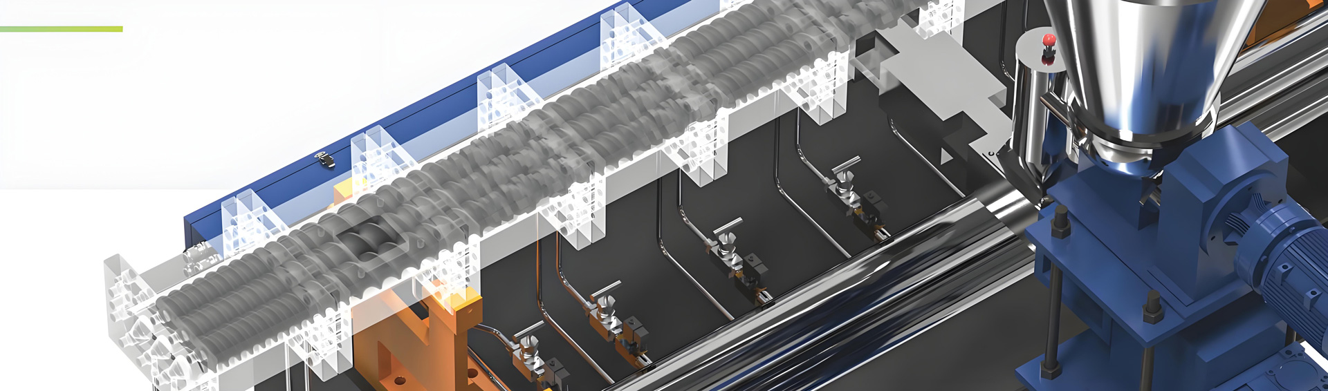
Extruder Components
Abnormal Noise from Motor
Possible Causes: Damaged bearings; insufficient lubrication.
Solution: Use grease gun to replenish grease.
Die Head Blockage
Possible Causes: Insufficient heating; foreign material blockage; high pressure at screen changer.
Solution: Check heater status, adjust temperature, or clean die head; replace filter screen.
Material Overflow from Natural Vent Port
Possible Cause: Improper screw design causing poor material flow through this section.
Solution: Adjust screw configuration and optimize vent zone design.
Material Overflow from Vacuum Vent
Symptom: Excessively high pressure shown on gauge.
Possible Cause: Screen changer is clogged with material and needs cleaning.
Solution: Check whether melt temperature is sufficient; inspect screen changer pressure.
Sudden Shutdown with Alarm
Possible Causes: Overfeeding; motor current overload; die head blockage, etc.
Solution: Check die head heater temperature and filter screen; clean foreign material from barrel.
Strand Breakage During Pelletizing
Possible Causes: Improper material ratio (excessive additives, insufficient plastic); uneven feeding or poor plastification (uneven temperature or low shear); die head blockage; poor vacuum venting; raw materials contain impurities.
Solution: Adjust material moisture; optimize formulation and feeding stability; adjust plastification zone temperature; clean die and filter screen; check vacuum sealing and venting.
Backflow or Leakage of Material from Feeder or Vent Port
Possible Causes: Improper screw element configuration (missing or misplaced reverse threads); feeding rate exceeds screw conveying capacity; barrel wear reduces sealing performance.
Solution: Inspect screw configuration; reduce feeding speed or segment feeding; check barrel wear, repair or replace as necessary.
Vacuum System Failure/Abnormal Vacuum Gauge Display/Poor Exhaust Effect/Insufficient Vacuum Degree
Possible Causes: Vacuum line clogged by condensed material or dust; aged sealing rings; vacuum tank water level too low or too high.
Solution: Regularly disassemble and clean vacuum pipelines, adding a filter; replace heat-resistant silicone seals and tighten joints; maintain water level in the vacuum tank at halfway.
Vibrating Screen Rusting (201 Stainless Steel)
Possible Causes: Water stains not cleaned promptly after shutdown; water or materials contain acidic or alkaline components.
Solution: Wipe off water immediately after machine stops; upgrade to 304 stainless steel for better corrosion resistance.
Installation and Precautions of the Loss-in-Weight/Gravimetric Feeder
- Mount directly above the twin screw extruder’s feeding port;
- Ensure a level and sturdy support platform;
- Use a flexible connector (rubber sleeve) to reduce vibration and protect weighing accuracy;
- After setup, connect power and signal cables, follow manual for system initialization and calibration with standard weights (e.g. 5kg, 10kg);
- Run a dry test to ensure feeding is stable and accurate.
Severe Screw Wear
Symptom: Reduced extrusion throughput.
Possible Causes: Processing abrasive materials (e.g. glass fiber, calcium carbonate, carbon black); poor mixing.
Solution: Check screw and barrel for wear; replace worn components including kneading blocks and sleeves.
Material Not Fully Melted
Possible Cause: Temperature setting too low.
Solution: Raise heating zone temperatures; check if screw design suits current material.
Material Bridging
Possible Cause: Material granule or powder structure causes clogging/bridging.
Solution: Granule bridging → install pneumatic hammer; powder bridging → use vertical mixer or vibration-assisted feeder; glass fiber bridging → use pneumatic hammer for short fibers; install screw-based bridge-breaker for long or elastic fibers.
Screw Jamming
Possible Causes: Material unmelted; foreign objects entered barrel; added heavy CaCO₃ and the material is not discharged cleanly after the machine is shut down; sleeve damaged.
Solution: Increase the temperature; remove the screw and clean/repair accordingly.
Vacuum Exhaust System Not Working
Possible Causes: Vacuum pump failure; exhaust port blockage; poor sealing.
Solution: Inspect vacuum pump operation; clean exhaust ports; check sealing rings, fasteners, and vacuum tank water level.
High Energy Consumption/ Decreased Efficiency
Possible Causes: Poor thermal insulation; mismatch in screw design; inefficient lubrication system; worn components.
Solution: Improve insulation; optimize screw design; inspect and maintain lubrication system.
Unable to Achieve Target Output Capacity/Capacity is Unstable
Possible Causes: Unoptimized formulation or process; improper temperature settings.
Solution: Adjust formulation and processing parameters.
The Output Shafts of Gearboxes A and B are Not Aligned Horizontally
Possible Cause: Gearbox frame is cast, not CNC-milled, which may result in minor misalignments (few millimeters); same as brands like Coperion, KY, CPM, USEON.
Solution: Use shims to align the output shafts; after adjustment, most shafts can be leveled accurately.


Circulating Water Setup and Pipe Dimensions
Cooling water: cooling tower; water chiller.
Parts that need to be cooled: Gearbox, use a plate heat exchanger, with high heat exchange efficiency, must use filtered clean water, it requires a complete set of replacement after blockage; water tank for barrel, use a tubular heat exchanger; both of water-cooling strand/water-ring hot pelletizing system need to add a cooling tower.
The water come from Chiller is connected with HEAT EXCHANGER only, it’s used to cooling the gearbox, barrel and water tank.
The water come from Water Tower is used to fill the water tank with cycled cold water to keep the water temperature.
Water Pipe Dimensions Reference:
Models SL-303 to SL-311: ¾ inch pipes;
Models SL-408 to SL-421: ¾ inch pipes;
Models SL-509 to SL-542: 1 inch pipes.
Gearbox Lubrication Oil Type, Oil Level, Recommended Oil Filling Volumes and Maintenance Interval
Lubricant Model: LCK-220 Medium-duty Gear Oil.
Oil Level: Should just cover the middle of the sight gauge.
Oil Change Cycle: First change after 3 months, then every 6 months.
Recommended Oil Filling Volumes by Model
| Machine Model | KTE-20A | KTE-25D | KTE-36B | KTE-36D | KTE-50B | KTE-52B |
| Oil Filling Volumes | ~5L | ~10L | ~40L | ~40L | ~60L | ~60L |
| Machine Model | KTE-52D | KTE-65B | KTE-65D | KTE-75B | KTE-75D | KTE-95B |
| Oil Filling Volumes | ~60L | ~90L | ~80L | 120~130L | 80~90L | 200~240L |
Gearbox Oil Filter Model and Service Life
1
2
Feeder Output Measurement, Gearbox Greasing and Maintenance
Feeder output Measurement: Power on the feeder and add materia; run at 5Hz for 1 minute, weigh output; multiply accordingly to estimate full-load capacity at 50Hz (60Hz). For example, if the speed is 5Hz and the material is 1kg per minute, the following table can be derived:
| Feeding Speed (Hz) | 5Hz | 10Hz | 15Hz | 20Hz | 25Hz | 30Hz | 35Hz | 40Hz | 45Hz | 50Hz |
| Capacity/Min(Kg) | 1 | 2 | 3 | 4 | 5 | 6 | 7 | 8 | 9 | 10 |
| Capacity/Hour(Kg) | 60 | 120 | 180 | 240 | 300 | 360 | 420 | 480 | 540 | 600 |
Gearbox Greasing: Add oil according to the specified oil level. If the oil is insufficient, lubrication will be inadequate, reducing the service life of components;If the oil is excessive, it may cause overheating, increased energy consumption, and faster oil deterioration, which can also lead to lubrication failure and damage to parts. If there is oil leakage in the gearbox, the sealing gasket (or ring) should be replaced promptly to ensure proper lubrication oil volume.
Recommended Maintenance: Re-grease monthly and check regularly.
Coupling Nylon Pin Replacement
Coupler auto-disengages upon overload, requires manual reset.
Replacement Steps: Remove coupling cover; pull out worn nylon pin and insert new one.


Refer to replacement tutorial video.
Cleaning and Replacement Guide of Solenoid Valve, Needle Valve, and Barrel When Barrel Cooling Performance Deterioration
Possible Causes: Blockage or rust inside valves.
Cleaning Method
Solenoid Valve and Needle Valve: Remove and rinse with clean water
Barrel: Regular machine operation prevents rust buildup, clean with acidic solvent after disassembly.
Reference picture of the needle valve:

Refer to the disassembly video of solenoid valve.
Self-Locking Spline Sleeve Installation Guide
Refer to installation tutorial video.
Remove and Install Screws Guide
Equipment Installation Leveling Method
Adjust base feet to ensure machine is level and stable.
Quick-Open Screen Changing: Opening and Replacing the Filter Screen, and Filter Screen Size Reference
Loosen bolts → remove filter plate → replace the filter.
Filter size

Refer to the operation video for specific instructions.
Operation and Filter Screen Replacement Method of Plate-Type Screen Changer, and Filter Screen Size Reference
Steps: Add oil → connect power → begin the operation. Green indicates a safe level, while red marks the maximum limit. Then pull the lever to change the screen.


Filter size

Refer to installation tutorial video.
Method for Connecting and Assembling an Independent Circulating Water System for the Vacuum Pump, Including Pipe Dimensions
Connect cooling loop before turning on vacuum pump; use separate water tank with filtration to keep water clean.


Pipe Size
Method for Handling Material Leakage at the Exhaust Port
Remove vent pipe → clean excess material → reinstall vacuum exhaust device → apply sealant.
Refer to operation video.
Pelletizing System
Coarse Pellets
Possible Causes: Poor plastification (low temp or shear), high moisture in material, poor lubricant ratio, screw wear.
Solution: Raise melt temperature; pre-dry material; adjust lubricant ratio.
Inconsistent Pellet Size
Possible Causes: Feeding fluctuation; unstable melt temperature or pressure.
Solution: Stabilize main feeding; maintain consistent process conditions.
Method of Strand Pulling in Strand Pelletizing
Refer to the video for details.
Installation and Blade Replacement Guide for Water-ring Hot-face Cutting Pelletizer
Refer to setup video tutorial.
Underwater Cutting System Die Head Cleaning and Start-Up Operation
1
How to Adjust Pelletizer Based on Material Properties
- 1
Pelletizer Blades or Holders Rusting
Possible Causes: Components are not stainless steel; water residue left after use.
Solution: Upgrade to stainless steel base; dry all parts after shutdown.