Introduction
Plastic reinforcing and toughening masterbatch production represents one of the most technically demanding segments in the compounding industry, requiring equipment capable of achieving exceptional dispersion accuracy while maintaining consistent product quality. High precision twin screw extruders designed for these applications must deliver precise control over processing parameters, ensure homogeneous distribution of reinforcing agents, and maintain tight tolerances for composition consistency.
Reinforcing masterbatch formulations incorporate high-performance fibers such as glass fibers, carbon fibers, or natural fibers that dramatically improve mechanical properties including tensile strength, flexural modulus, and dimensional stability. Toughening agents including core-shell rubber particles, elastomeric modifiers, and impact modifiers enhance ductility and impact resistance, creating balanced property profiles suitable for demanding applications in automotive, aerospace, and engineering plastics sectors.
The combination of reinforcing fibers with toughening agents creates unique processing challenges that demand specialized equipment with exceptional control capabilities. Modern high precision twin screw extruders from Kerke Extrusion Equipment Company incorporate advanced screw designs, precise temperature control systems, and sophisticated monitoring equipment necessary for these demanding applications. This comprehensive guide explores the complete production process for reinforcing and toughening masterbatch using high precision equipment.
Formulation Proportions (Different Types)
Formulation development for reinforcing and toughening masterbatch requires careful consideration of fiber loading levels, fiber length retention, toughening agent selection, and the synergistic interactions between reinforcing fibers and toughening phases. Different application requirements dictate varying concentration ranges and additive combinations.
Glass Fiber Reinforced Formulations
Glass fiber reinforced formulations represent the most widely used type of reinforcing masterbatch due to excellent cost-performance ratio and established processing knowledge. Standard formulations contain 20% to 40% glass fibers with lengths typically ranging from 3mm to 6mm, depending on the desired balance of reinforcement and processability.
Automotive exterior applications requiring high stiffness and dimensional stability often employ formulations with 30% to 40% glass fibers of 4mm to 6mm length. These high loading levels provide tensile modulus improvements exceeding 400% compared to unfilled polymers. However, processing becomes increasingly challenging at higher fiber loadings, requiring specialized equipment to maintain fiber length retention while achieving adequate dispersion.
When combined with toughening agents, glass fiber formulations typically include 5% to 15% impact modifiers such as core-shell rubber particles or maleic anhydride grafted polymers. The toughening agent concentration must be carefully balanced against fiber loading, as higher fiber content can reduce toughening effectiveness. Most manufacturers target toughening agent concentrations of 8% to 12% in formulations containing 25% to 35% glass fibers.
Carbon Fiber Reinforced Systems
Carbon fiber reinforced masterbatch provides exceptional stiffness and electrical conductivity improvements, making it valuable for automotive lightweighting and electromagnetic shielding applications. Standard formulations contain 10% to 25% carbon fibers with typical lengths of 3mm to 6mm, depending on the electrical conductivity and mechanical property requirements.
Structural applications requiring maximum stiffness may employ formulations with 20% to 25% carbon fibers, providing tensile modulus improvements of 600% to 800% compared to base polymers. Electrical conductivity applications requiring specific conductivity targets may use 10% to 20% carbon fibers, with the exact concentration determined by percolation threshold calculations.
Toughening agent selection for carbon fiber formulations differs from glass fiber systems due to the different fiber surface chemistry. Maleic anhydride grafted polymers demonstrate superior interfacial adhesion with carbon fiber surfaces, enabling effective toughening at lower concentrations of 3% to 8%. Core-shell rubber particles may also be used at concentrations of 5% to 12%, depending on the desired impact resistance improvement.
Natural Fiber Reinforced Compositions
Natural fiber reinforced masterbatch, including wood fibers, hemp, and flax, represents growing market segments driven by sustainability initiatives. These formulations typically contain 15% to 30% natural fibers with lengths from 1mm to 4mm, balancing reinforcement with processing challenges unique to natural fibers.
Automotive interior applications requiring natural appearance and improved acoustic performance often employ formulations with 20% to 25% wood fibers. These formulations provide tensile modulus improvements of 200% to 300% while reducing environmental impact. However, natural fibers present unique challenges including moisture absorption, thermal degradation, and fiber-matrix adhesion issues.
Toughening agent selection for natural fiber formulations requires consideration of thermal stability limitations and moisture sensitivity. Maleic anhydride grafted polymers at concentrations of 5% to 15% improve fiber-matrix adhesion and provide additional toughening benefits. Core-shell rubber particles may also be incorporated at 5% to 12%, though thermal processing must be carefully controlled to prevent natural fiber degradation.
Hybrid Fiber Reinforced Formulations
Advanced applications requiring balanced property profiles often employ hybrid fiber formulations combining different fiber types to achieve synergistic effects. These hybrid systems may contain total fiber loadings of 25% to 50%, with individual fiber types optimized for specific property requirements.
Automotive structural components requiring both high stiffness and impact resistance may employ formulations containing 20% glass fibers and 10% carbon fibers, providing stiffness improvements from the glass fibers and electrical conductivity from the carbon fibers. The hybrid approach can achieve superior performance characteristics compared to single-fiber formulations at equivalent total loading levels.
Toughening agent requirements for hybrid fiber formulations depend on the specific fiber combination and target application. Maleic anhydride grafted polymers at 5% to 12% provide good interfacial adhesion with both fiber types. Core-shell rubber particles at 8% to 15% may be added for additional impact resistance, though compatibility with both fiber types must be verified through application testing.
Core-Shell Rubber Toughening Systems
Core-shell rubber particles represent advanced toughening agents that provide exceptional impact resistance without compromising other mechanical properties. These particles typically consist of a rubbery core encapsulated in a rigid shell material, creating a morphology that provides energy absorption during impact events.
Standard core-shell rubber formulations contain 10% to 20% particles with typical core-shell diameters ranging from 50nm to 500nm. Automotive applications requiring exceptional impact resistance, particularly at low temperatures, may employ formulations with 15% to 20% core-shell rubber particles to achieve Izod impact values exceeding 800 J/m.
When combined with reinforcing fibers, core-shell rubber concentrations typically range from 5% to 15% depending on the fiber loading and desired property balance. High fiber loading formulations (35% to 40%) typically use 5% to 8% core-shell rubber to maintain processability while providing adequate toughening. Lower fiber loading formulations (15% to 25%) may use 10% to 15% core-shell rubber to achieve maximum impact resistance.
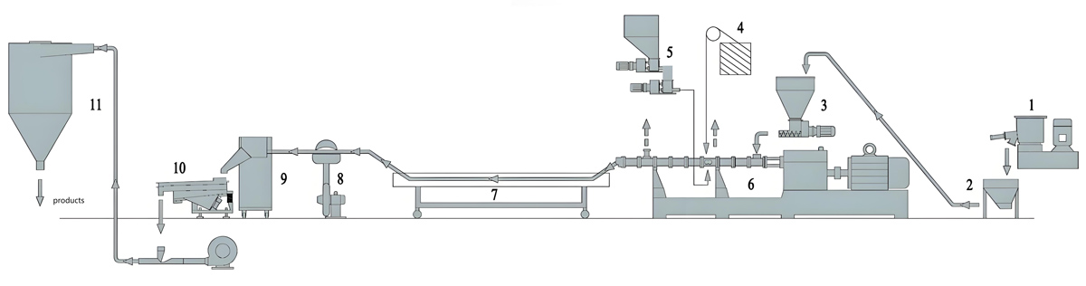
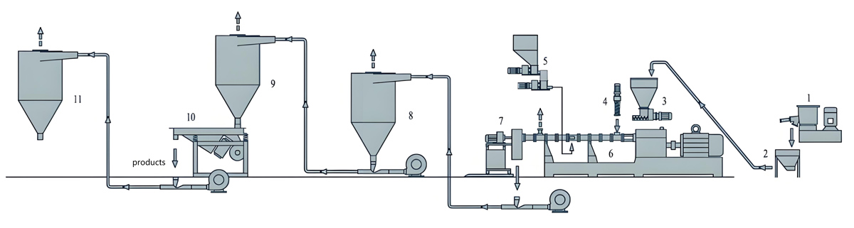
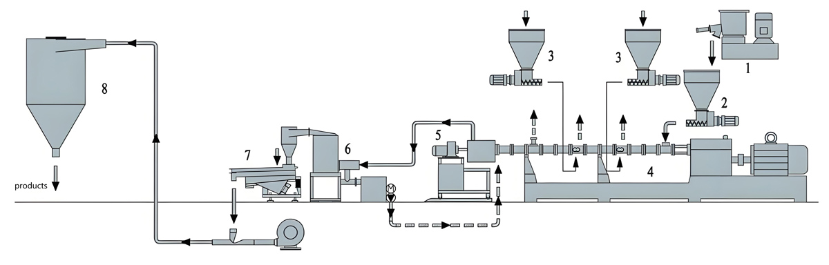
Production Process
The production process for reinforcing and toughening masterbatch on high precision equipment requires carefully controlled conditions to achieve exceptional dispersion of reinforcing fibers while maintaining fiber length retention and toughening agent effectiveness. High throughput demands equipment capable of delivering consistent quality with tight composition tolerances.
Fiber Handling and Preparation
Proper fiber handling represents a critical aspect of reinforcing masterbatch production, as fibers are sensitive to damage during handling and feeding. Glass fibers and carbon fibers typically arrive in roving or chopped form, requiring specialized handling systems to prevent fiber breakage and maintain aspect ratio.
Chopped fiber feeding systems must minimize fiber damage while ensuring consistent feeding rates to the extruder. Low-shear feeding devices with gentle material handling preserve fiber length, with typical systems achieving fiber breakage rates below 5% during feeding. Feeder designs should prevent fiber bridging and ensure consistent bulk density for accurate weight-based feeding.
Natural fibers require additional preparation steps including moisture content reduction to below 0.1% before processing. Drying temperatures typically range from 80°C to 100°C for 4 to 6 hours, depending on fiber type and initial moisture content. Proper drying prevents steam generation during extrusion that could cause voids or surface defects in the final product.
Precision Feeding Systems
High precision feeding systems are essential for maintaining consistent composition in reinforcing and toughening masterbatch formulations. Gravimetric feeding systems with accuracy within ±0.2% of setpoint provide the tight control necessary for formulations with multiple additive streams.
Multiple feeder configurations are typically employed, with separate feeders for carrier resin, reinforcing fibers, toughening agents, and other additives. Carrier resin feeders typically have capacities from 50 to 500 kg/hr depending on the extruder size. Fiber feeders require special design to maintain consistent bulk density and feeding accuracy while minimizing fiber damage.
Loss-in-weight feeding technology provides the highest accuracy for minor components such as coupling agents and processing aids. These specialized feeders can achieve accuracy within ±0.1% of setpoint, ensuring precise control of additives that constitute less than 2% of the total formulation.
Advanced Screw Configuration
Screw configurations for reinforcing and toughening masterbatch must achieve excellent dispersion of fibers while maintaining fiber length and achieving homogeneous distribution of toughening agents. The configuration varies based on fiber type, loading level, and desired property profile.
Standard configurations incorporate conveying elements in the feed section to ensure consistent material transport, followed by gentle melting zones that minimize fiber damage. The initial mixing zone employs distributive mixing elements such as gear mixers to achieve initial dispersion without excessive shear that could break fibers.
For formulations with high fiber loadings (35% to 50%), screw configurations often include multiple gentle mixing sections separated by conveying sections to prevent fiber breakage. The total mixing length provided by L/D ratios of 48:1 to 60:1 ensures adequate dispersion while preserving fiber length.
Temperature Profile Precision
Temperature control is particularly critical for reinforcing and toughening masterbatch production, as thermal conditions significantly impact fiber-matrix adhesion, toughening agent effectiveness, and fiber degradation. High precision extruders provide temperature control within ±0.5°C of setpoint across all barrel zones.
Standard temperature profiles for glass fiber reinforced formulations range from 200°C to 240°C, with specific temperatures depending on the carrier resin and fiber type. Lower temperatures in the feed and melting zones (200°C to 220°C) reduce fiber damage during initial processing. The mixing and die zones operate at higher temperatures (220°C to 240°C) to ensure proper matrix flow and fiber wetting.
Natural fiber formulations require more restrictive temperature profiles, typically ranging from 180°C to 210°C to prevent thermal degradation of the natural fibers. Carbon fiber formulations may use higher temperatures up to 260°C when processing high-performance matrix resins, though the carbon fibers themselves are thermally stable at these temperatures.
Fiber Dispersion Techniques
Achieving excellent fiber dispersion while maintaining fiber length represents the key challenge in reinforcing masterbatch production. Advanced mixing techniques and process optimization enable manufacturers to achieve optimal dispersion without excessive fiber damage.
Gentle distributive mixing elements provide the primary mechanism for achieving fiber dispersion. Gear mixers, Maddock mixers, and specialized distributive elements create flow patterns that separate fiber bundles and distribute individual fibers throughout the matrix without the high shear that would break fibers.
The placement and configuration of mixing elements along the screw length significantly impacts dispersion quality and fiber retention. More aggressive mixing elements positioned after initial fiber wetting improve dispersion without excessive fiber breakage. The balance between mixing intensity and fiber preservation requires careful optimization for each specific formulation.
Toughening Agent Incorporation
Toughening agent incorporation strategies vary based on the specific toughening mechanism and compatibility with the fiber-reinforced matrix. Proper incorporation is essential to achieve the desired toughening effect without compromising fiber dispersion or matrix properties.
Core-shell rubber particles and elastomeric modifiers are typically fed through main feed or side feeders, depending on thermal sensitivity and desired distribution. Side feeding downstream of the melting zone reduces thermal exposure for temperature-sensitive toughening agents while allowing sufficient mixing time for homogeneous distribution.
Maleic anhydride grafted polymers may be introduced at various points depending on the desired interfacial modification strategy. Introduction upstream of the fiber feeding point enables grafting onto fiber surfaces, improving fiber-matrix adhesion. Introduction downstream of fiber feeding provides matrix modification without affecting fiber surfaces.
Die Design and Strand Formation
Die design for reinforcing and toughening masterbatch must accommodate the high viscosity and abrasive nature of fiber-filled melts while producing uniform strands for pelletizing. Specialized die materials and designs help maintain performance and extend service life.
Strand dies for fiber-reinforced formulations typically feature wear-resistant materials such as tungsten carbide or specialized steel alloys to withstand abrasive fiber wear. Hole diameters range from 2mm to 6mm, with hole counts from 4 to 50 depending on throughput requirements. The die land length is optimized to provide proper melt conditioning without excessive pressure drop.
Die design considerations include minimizing flow restrictions that could cause additional fiber damage, ensuring uniform flow distribution across all strands, and providing adequate melt strength for strand formation. Specialized breaker plates and distributor channels help achieve uniform strand dimensions despite the high melt viscosity.
Pelletizing with Fiber Preservation
Pelletizing fiber-reinforced masterbatch presents unique challenges to maintain fiber length and prevent pellet damage. Standard pelletizing techniques must be adapted to accommodate the abrasive and brittle nature of fiber-filled materials.
Water ring pelletizing is generally preferred for fiber-reinforced formulations as it produces spherical pellets that minimize fiber protrusion and pellet damage. Cutter speeds and water flow patterns must be optimized to achieve clean pellet separation without excessive fiber breakage. Typical cutter speeds range from 2000 to 4000 RPM, depending on pellet size and throughput rate.
Strand pelletizing may be used for formulations with longer fibers or specific pellet shape requirements, though fiber damage during strand handling and pelletizing can be higher. Strand guides must be designed to minimize fiber abrasion and prevent strand breakage that could cause pellet size variations.
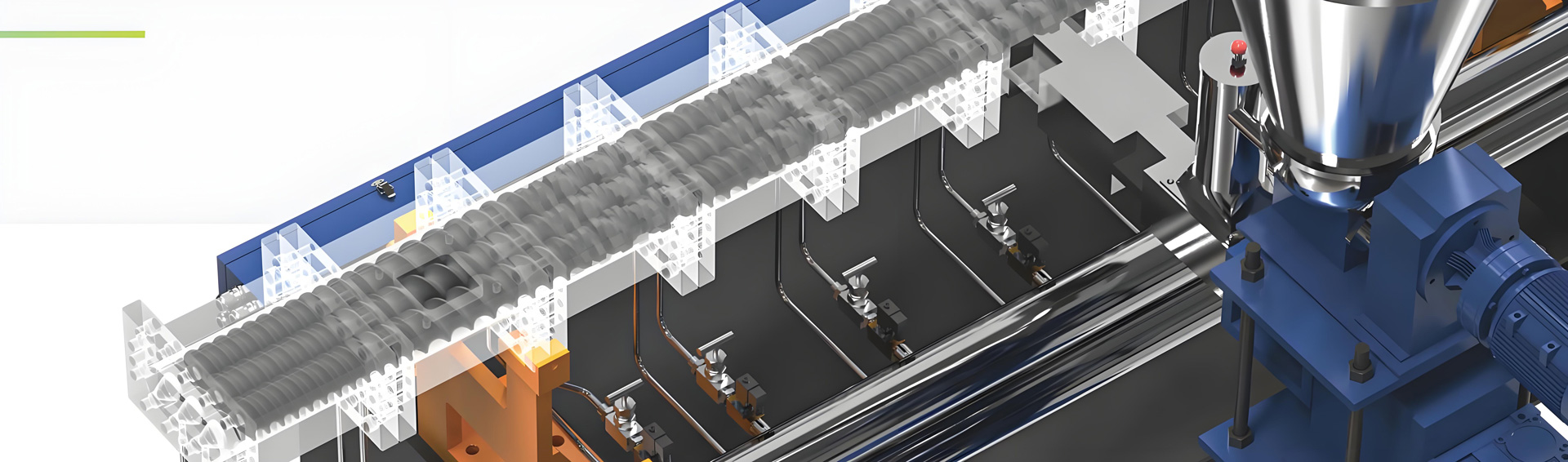
Production Equipment Introduction
High precision twin screw extruders designed for reinforcing and toughening masterbatch production incorporate specialized features to achieve exceptional dispersion quality while maintaining tight composition tolerances and fiber length preservation.
KTE Series High Precision Extruders
The KTE Series parallel twin screw extruders from Kerke Extrusion Equipment Company include models specifically designed for high precision compounding applications. These extruders feature screw diameters from 30mm to 75mm, providing throughput capacities from 100 to 800 kg/hr for reinforcing and toughening formulations.
The KTE-30 model with 30mm screw diameter delivers typical throughput rates of 100 to 150 kg/hr for fiber-reinforced formulations. The KTE-40 model with 40mm screw diameter achieves 150 to 300 kg/hr. The KTE-50 model with 50mm screw diameter provides 300 to 500 kg/hr. The KTE-75 model with 75mm screw diameter delivers 500 to 800 kg/hr capacity.
All high precision models feature L/D ratios of 48:1 to 60:1, providing the extended mixing length necessary for achieving excellent dispersion while preserving fiber length. Advanced drive systems include servo motors with torque control capabilities, enabling precise regulation of screw speed and power input.
Precision Temperature Control Systems
High precision extruders incorporate advanced temperature control systems with multiple independent zones and sophisticated control algorithms. Standard configurations include 10 to 14 heating zones along the barrel length, each with multiple heating elements arranged circumferentially for uniform heating.
Temperature control accuracy of ±0.5°C is achieved through PID control algorithms with adaptive tuning capabilities. Each zone features independent cooling systems using air or water circulation to provide rapid temperature response and precise temperature stability. Multiple temperature sensors per zone ensure accurate measurement and control.
The die zone temperature control is particularly critical for fiber-reinforced formulations, as precise control prevents fiber degradation and ensures consistent melt viscosity. Die designs incorporate multiple heating zones with independent control, enabling precise temperature gradients across the die face.
Advanced Feeding Integration
High precision extruders integrate with sophisticated feeding systems capable of handling multiple material streams with exceptional accuracy. Gravimetric feeding systems with digital load cells provide the accuracy necessary for maintaining tight composition tolerances.
Multiple feeder mounting points along the barrel enable flexible feeding strategies for different additives. Standard configurations include 2 to 6 feeder ports, with additional ports available as options. Loss-in-weight feeding technology provides the highest accuracy for minor components, achieving accuracy within ±0.1% of setpoint.
Fiber feeding systems incorporate special features to minimize fiber damage while maintaining feeding accuracy. Low-shear hopper designs, gentle auger configurations, and vibration-assisted feeding help maintain fiber length and consistent bulk density. Feeder capacities range from 10 to 200 kg/hr, matching the requirements for various production scales.
Precision Monitoring and Control
High precision extruders incorporate advanced monitoring and control systems that provide real-time visibility into process conditions and enable automated control based on predefined parameters. These systems help maintain consistent product quality and enable rapid detection of process variations.
Monitoring systems track critical parameters including temperature profile, screw speed, torque, melt pressure, and feeder rates. Advanced process control algorithms maintain optimal conditions despite variations in raw material properties or ambient conditions. Automated recipe management enables quick changeover between different formulations while maintaining process precision.
Integrated data logging and analysis capabilities provide detailed records of processing conditions, enabling traceability and process optimization. Remote monitoring capabilities enable supervision from central control rooms and support remote troubleshooting.
Wear-Resistant Components
Processing abrasive fibers such as glass and carbon requires specialized wear-resistant components throughout the extruder system. These specialized materials and designs extend service life and maintain processing precision.
Screw and barrel surfaces may be treated with wear-resistant coatings or manufactured from specialized alloys to withstand abrasive wear. Tungsten carbide coatings provide exceptional wear resistance in high-wear areas such as mixing zones and die sections. Advanced screw designs may include wear plates or sleeves that can be replaced when worn, avoiding complete screw replacement.
Die components and breaker plates manufactured from tungsten carbide or hardened steel alloys maintain die geometry and prevent flow disturbances that could affect product quality. Regular inspection and replacement of wear components maintains processing precision and product quality over extended operation.
Parameter Settings
Optimal parameter settings for high precision reinforcing and toughening masterbatch production must balance dispersion quality with fiber preservation and toughening agent effectiveness. These parameters require careful optimization based on formulation characteristics and equipment capabilities.
Temperature Profile Optimization
Temperature profiles vary significantly based on the specific formulation and desired property profile. For glass fiber reinforced formulations containing 30% fibers and 10% toughening agent, typical temperature profiles include: feed zone 200°C to 210°C, melting zone 210°C to 220°C, mixing zone 220°C to 235°C, and die zone 230°C to 240°C.
Carbon fiber formulations often use higher temperature profiles, particularly when processing high-performance matrix resins. For polyetheretherketone (PEEK) based formulations, temperature profiles may range from 320°C to 380°C. However, many carbon fiber formulations use standard engineering resins with temperature profiles similar to glass fiber systems.
Natural fiber formulations require the most restrictive temperature profiles to prevent thermal degradation. Typical profiles range from 180°C to 210°C, with precise control critical to prevent discoloration and odor development that indicate fiber degradation.
Screw Speed and Throughput Precision
Screw speed and throughput rate must be optimized to achieve adequate mixing and dispersion while preserving fiber length. For high precision operations, screw speeds typically range from 150 to 350 RPM, with the specific speed determined by fiber type and loading level.
Gentle screw speeds of 150 to 250 RPM are used for formulations with long fibers or high fiber loadings to minimize fiber breakage. Higher speeds of 250 to 350 RPM may be used for formulations with shorter fibers or lower fiber loadings where dispersion quality is the primary concern.
Throughput rates depend on screw diameter and formulation characteristics. The KTE-30 model typically operates at 200 to 250 RPM, achieving 100 to 150 kg/hr. The KTE-40 model operates at 180 to 280 RPM for 150 to 300 kg/hr. Throughput must be optimized to maintain adequate residence time for dispersion without excessive thermal exposure.
Feeding Rate Precision
Feeding rate precision is critical for maintaining consistent composition in formulations with multiple additive streams. Gravimetric feeders typically maintain accuracy within ±0.2% of setpoint, with loss-in-weight feeders achieving ±0.1% accuracy for minor components.
For a formulation containing 35% glass fibers and 10% toughening agent, a ±0.2% feeder accuracy represents ±0.07% absolute concentration variation for the fibers and ±0.02% for the toughening agent. These tight tolerances enable consistent product quality and property performance.
Regular feeder calibration is essential to maintain this level of accuracy, with calibration frequencies typically monthly for high precision operations. Monitoring feeding performance through statistical process control helps detect deviations before they impact product quality.
Mixing Element Configuration
The configuration and placement of mixing elements along the screw length significantly impacts dispersion quality and fiber preservation. Different mixing element types provide varying levels of distributive and dispersive mixing, with appropriate selection depending on formulation requirements.
Gentle distributive elements such as gear mixers provide fiber separation and distribution without excessive shear. These elements are typically positioned in the initial mixing zone after fiber wetting. More aggressive dispersive elements may be used in later mixing zones to break fiber bundles and achieve complete dispersion.
The total number and placement of mixing elements must be optimized for each formulation. Formulations with high fiber loadings typically use more mixing elements with gentler geometries to achieve dispersion without fiber damage. Lower loading formulations may use fewer, more aggressive mixing elements.
Die and Pelletizing Settings
Die and pelletizing equipment settings must be optimized to achieve uniform pellet size while minimizing fiber damage and maintaining pellet quality. Strand dimensions, water flow patterns (for water ring pelletizing), and cutter settings all require careful optimization.
Strand die settings include melt temperature control to ensure proper strand formation and minimize fiber damage. Die temperature should be maintained at the lowest temperature that provides adequate melt flow, typically 5°C to 10°C above the mixing zone temperature. Strand dimensions should be optimized for pelletizing equipment, with diameters of 2mm to 4mm typical for fiber-reinforced formulations.
Water ring pelletizer settings include cutter speed, water flow rate, and water temperature. Cutter speeds of 2000 to 4000 RPM provide clean pellet separation for typical formulations. Water flow rates of 30 to 150 m³/hr ensure adequate cooling and pellet solidification. Water temperature should be maintained at 15°C to 25°C to achieve rapid solidification without thermal shock.
Equipment Pricing
Investment in high precision twin screw extruder equipment for reinforcing and toughening masterbatch production represents substantial capital expenditure. Understanding the cost structure enables proper budgeting and investment planning.
Main Extruder Investment
KTE Series high precision twin screw extruders represent the largest component of total investment. The KTE-30 model with 30mm screw diameter typically costs from $150,000 to $250,000 depending on configuration and options. The KTE-40 model with 40mm screw diameter ranges from $200,000 to $350,000. The KTE-50 model with 50mm screw diameter typically costs from $300,000 to $450,000. The KTE-75 model with 75mm screw diameter represents the largest investment, typically from $500,000 to $800,000.
These prices include the basic high precision extruder configuration with advanced temperature control, precision drives, and sophisticated control system. Optional features such as specialized screw configurations, wear-resistant coatings, and enhanced monitoring systems increase the total investment by 15% to 30% depending on selected options.
Feeding System Costs
Precision feeding systems represent significant additional investment, particularly for formulations requiring multiple additive streams. Gravimetric feeders with digital load cells and high accuracy typically cost from $20,000 to $60,000 each depending on capacity and sophistication.
Fiber feeding systems with specialized low-shear designs and bulk density control typically cost from $30,000 to $80,000. Loss-in-weight feeding systems for minor components with exceptional accuracy cost from $15,000 to $40,000. A complete high precision feeding system for reinforcing and toughening masterbatch may cost from $100,000 to $250,000 depending on the number of feeders and their capabilities.
Pelletizing System Investment
Pelletizing systems for fiber-reinforced formulations require specialized designs to handle abrasive materials and minimize fiber damage. Water ring pelletizing systems for high precision applications cost from $80,000 to $200,000 depending on capacity and configuration.
Strand pelletizing systems may be used for certain applications and typically cost from $60,000 to $150,000, including specialized die, strand handling equipment with abrasion-resistant materials, and cooling system. However, water ring systems generally provide better performance for fiber-reinforced formulations in terms of fiber preservation and pellet quality consistency.
Complete Line Investment
Complete high precision production lines for reinforcing and toughening masterbatch, including extruder, precision feeding systems, pelletizing equipment, and all auxiliary systems, typically represent investments from $400,000 to $1,500,000. The specific investment depends on production capacity, formulation complexity, and level of precision required.
Additional costs including installation, commissioning, operator training, and initial raw materials add 10% to 15% to the base equipment investment. These costs must be considered when planning the total capital investment for a high precision production line.
Production Problems and Solutions
High precision production of reinforcing and toughening masterbatch presents unique challenges that require prompt identification and resolution to maintain product quality and processing precision.
Fiber Damage and Breakage
Problem Description: Reinforcing fibers show excessive breakage during processing, resulting in reduced fiber length and compromised reinforcement efficiency. This problem is particularly severe for long-fiber formulations where aspect ratio significantly impacts mechanical properties.
Causes: Excessive screw speed creates high shear forces that break fibers. Aggressive mixing elements with narrow clearances cause fiber damage. Temperature profile that is too low increases melt viscosity, increasing fiber-matrix interactions that cause breakage. Feeding systems that subject fibers to high shear during introduction.
Solutions: Reduce screw speed to decrease shear forces. Replace aggressive mixing elements with gentler distributive mixing designs. Increase temperature profile to reduce melt viscosity and fiber-matrix interactions. Modify feeding systems to minimize fiber damage during introduction.
Prevention Methods: Develop formulation-specific screw configurations optimized for fiber preservation. Establish screw speed limits based on fiber type and length. Implement regular inspection of mixing elements for wear that increases shear forces. Design feeding systems specifically for fiber handling.
Poor Fiber Dispersion
Problem Description: Fibers appear as agglomerates or show uneven distribution throughout the matrix, resulting in inconsistent mechanical properties and visible defects in final products. This problem often accompanies inadequate mixing or insufficient residence time.
Causes: Insufficient mixing elements along the screw length. Screw speed that is too low provides inadequate distributive mixing. Temperature profile that is too low reduces polymer mobility, hindering fiber wetting and dispersion. Inadequate residence time prevents complete fiber separation and distribution.
Solutions: Add or reposition mixing elements to enhance distributive mixing. Increase screw speed to improve mixing intensity while monitoring fiber breakage. Adjust temperature profile to increase polymer mobility, particularly in the mixing zone. Optimize throughput rate to provide adequate residence time for dispersion.
Prevention Methods: Develop mixing element configurations based on formulation requirements and dispersion specifications. Establish residence time specifications for each formulation type. Implement regular inspection of screw configuration to ensure mixing elements are properly positioned and not worn.
Toughening Agent Agglomeration
Problem Description: Toughening agents appear as agglomerates or show uneven distribution, resulting in inconsistent impact resistance and potential property defects in final products. This problem is particularly problematic for core-shell rubber particles and elastomeric modifiers.
Causes: Insufficient mixing prevents homogeneous distribution of toughening agents. Temperature profile that is too low reduces polymer mobility, hindering toughening agent wetting and dispersion. Toughening agent introduction point too far downstream prevents adequate mixing time. Inadequate toughening agent compatibility with matrix or fibers causes poor wetting.
Solutions: Increase mixing element intensity or add additional mixing elements. Increase temperature profile to improve polymer mobility and toughening agent wetting. Modify toughening agent introduction point to provide more mixing time. Evaluate toughening agent compatibility and consider alternative agents or coupling agents.
Prevention Methods: Develop toughening agent-specific introduction strategies and mixing configurations. Establish minimum residence time requirements for toughening agent dispersion. Test toughening agent compatibility before large-scale production. Implement quality control measures to detect agglomeration early.
Fiber-Matrix Interfacial Adhesion Issues
Problem Description: Mechanical properties fall below expected levels due to poor fiber-matrix interfacial adhesion. This problem manifests as reduced tensile strength, modulus, and impact resistance despite proper fiber loading and dispersion.
Causes: Insufficient coupling agent concentration or improper type for fiber-matrix combination. Temperature profile that is too low prevents proper coupling agent activation or fiber surface modification. Inadequate mixing prevents uniform coupling agent distribution. Fiber surface contamination from storage or handling prevents proper adhesion.
Solutions: Increase coupling agent concentration or evaluate alternative coupling agents. Increase temperature profile to ensure proper coupling agent activation. Optimize mixing to ensure uniform coupling agent distribution. Improve fiber storage and handling to prevent surface contamination.
Prevention Methods: Develop coupling agent specifications for each fiber-matrix combination. Establish temperature profiles that ensure proper coupling agent activation. Implement fiber quality control including surface condition monitoring. Develop formulation-specific mixing protocols.
Die Build-Up and Flow Disturbances
Problem Description: Polymer builds up on die surfaces or fiber deposits create flow disturbances, causing strand dimension variations and product quality issues. This problem is particularly common with abrasive fibers that can wear die surfaces and create turbulence.
Causes: Die surfaces become worn from abrasive fiber wear, creating turbulence points. Temperature profile that is too low causes premature solidification near die surfaces. Fiber deposits accumulate on die surfaces, disturbing flow patterns. Inadequate die geometry for high-viscosity fiber-filled melts.
Solutions: Replace worn die surfaces with wear-resistant materials. Increase die temperature to prevent premature solidification. Implement regular die cleaning to remove fiber deposits. Evaluate die geometry optimization for fiber-filled melt characteristics.
Prevention Methods: Use wear-resistant die materials such as tungsten carbide. Establish die temperature maintenance procedures. Implement regular die cleaning and inspection schedules. Design dies specifically for fiber-filled melt characteristics.
Pellet Quality Variations
Problem Description: Pellets show size variations, surface defects, or fiber protrusion that affects feeding and processing in downstream applications. This problem reduces product quality and can cause processing difficulties for customers.
Causes: Pelletizer settings including cutter speed and water flow patterns are not optimized for the formulation. Fiber length variations cause inconsistent pellet formation. Temperature variations affect pellet solidification and cutting characteristics. Die strand dimension variations cause pellet size inconsistencies.
Solutions: Optimize pelletizer settings for the specific formulation characteristics. Improve fiber length consistency through processing optimization. Implement tighter temperature control to ensure consistent strand characteristics. Optimize die design and operation for uniform strand dimensions.
Prevention Methods: Develop pelletizer setting specifications for each formulation type. Implement statistical process control for pellet dimensions. Maintain tight temperature control throughout the process. Regular die maintenance and optimization ensures consistent strand formation.
Maintenance and Care
High precision twin screw extruders require comprehensive maintenance programs to maintain processing precision and equipment performance. Preventive maintenance schedules must address the unique challenges posed by abrasive fibers and high precision requirements.
Daily Maintenance Procedures
Daily maintenance for high precision operations includes comprehensive inspection and verification of all critical systems. Operators should verify all temperature readings are within ±0.5°C of setpoint to ensure processing precision. Monitor screw speed and torque to detect any variations that could indicate developing problems.
Check all feeder readings to ensure feeding accuracy within specifications. Inspect die and pelletizing equipment for signs of wear or deposits that could affect product quality. Document all daily observations in maintenance logs to track trends and identify developing problems.
Weekly Maintenance Tasks
Weekly maintenance includes detailed inspection and preventive maintenance on precision components. Verify all belt drives and couplings for proper alignment and tension, as misalignment can affect processing precision. Inspect screw and barrel surfaces through access ports to identify wear patterns from abrasive fibers.
Test all temperature control systems for proper operation and accuracy. Check feeding systems for consistent performance and calibrate if necessary. Clean die surfaces and remove any fiber deposits that could affect flow characteristics. Verify pelletizer blade condition and alignment.
Monthly Maintenance Activities
Monthly maintenance includes calibration and more extensive inspection. Perform detailed calibration of all feeding systems using standard calibration weights. Verify temperature sensor accuracy using reference thermometers and adjust as necessary to maintain ±0.5°C accuracy.
Inspect mixing elements for wear patterns that could affect mixing precision or fiber preservation. Analyze torque and motor current trends to identify developing mechanical problems. Review maintenance logs to identify recurring issues that may require engineering solutions.
Quarterly and Semi-Annual Maintenance
Quarterly maintenance should include component replacement based on usage patterns and wear from abrasive fibers. Replace worn mixing elements, seals, and wear parts before they affect processing precision. Service gearboxes and drives according to manufacturer schedules, with particular attention to gear wear from abrasive contamination.
Semi-annual maintenance may include screw and barrel inspection and potential replacement. High precision extruders processing abrasive fibers typically require screw and barrel replacement after 5,000 to 10,000 operating hours, depending on fiber type and loading. Early replacement prevents gradual degradation of processing precision.
Feeding System Maintenance
Precision feeding systems require regular maintenance to maintain the tight feeding accuracy essential for high precision production. Gravimetric feeders require monthly calibration and regular sensor cleaning. Fiber feeding systems require regular inspection for wear and proper bulk density control.
Loss-in-weight feeders for minor components require particular attention to maintain ±0.1% accuracy. These systems typically require more frequent calibration, possibly weekly, to maintain this level of precision. Regular maintenance of load cells and sensors ensures continued accuracy.
FAQ
What is the maximum fiber loading for reinforcing masterbatch?
The maximum loading depends on fiber type, carrier resin, and equipment capabilities. Glass fiber formulations typically contain 20% to 40% fibers, though some applications may use up to 50% with specialized equipment and processing. Carbon fiber formulations typically contain 10% to 25% fibers, with higher loadings limited by cost and processing challenges. Natural fiber formulations usually contain 15% to 30% fibers due to moisture and thermal degradation limitations.
How do I maintain fiber length during processing?
Fiber length preservation requires gentle processing conditions throughout the production process. Use screw speeds low enough to minimize shear forces while still achieving adequate dispersion. Implement gentle mixing elements that provide distributive mixing without excessive shear. Maintain appropriate temperature profiles to reduce melt viscosity and fiber-matrix interactions. Use specialized feeding systems that minimize fiber damage during introduction.
What causes poor toughening agent dispersion?
Poor toughening agent dispersion typically results from insufficient mixing, inadequate residence time, or poor wetting. Mixing elements that are too few or improperly positioned prevent homogeneous distribution. Screw speeds that are too low provide insufficient distributive mixing. Temperature profiles that are too low reduce polymer mobility and toughening agent wetting. Introduction points too far downstream prevent adequate mixing time.
How do I achieve tight composition tolerances?
Tight composition tolerances require high precision feeding systems and regular calibration. Use gravimetric feeders with digital load cells providing accuracy within ±0.2% of setpoint. For minor components, use loss-in-weight feeders achieving ±0.1% accuracy. Implement regular feeder calibration, typically monthly for main feeders and weekly for minor component feeders. Monitor feeding performance through statistical process control.
What maintenance does high precision equipment require?
High precision equipment requires more frequent maintenance than standard equipment to maintain processing precision. Daily verification of temperature, screw speed, and feeder readings. Weekly inspection of critical components and cleaning. Monthly calibration of feeding systems and temperature sensors. Quarterly replacement of wear components based on abrasive fiber wear. Semi-annual to annual screw and barrel replacement depending on operating hours and fiber type.
How do I optimize dispersion while preserving fiber length?
Optimizing dispersion while preserving fiber length requires careful balance of processing parameters. Use gentle distributive mixing elements positioned after initial fiber wetting. Maintain screw speeds high enough for adequate mixing but low enough to minimize fiber breakage. Optimize temperature profiles to reduce melt viscosity and fiber-matrix interactions. Provide sufficient residence time for dispersion without excessive thermal exposure.
What causes die build-up in fiber-reinforced formulations?
Die build-up typically results from abrasive fiber wear creating turbulence points, fiber deposits accumulating on surfaces, and temperature issues causing premature solidification. Wear-resistant die materials and regular die cleaning help prevent build-up. Proper temperature control ensures melt remains fluid through the die. Regular die inspection identifies developing problems before they affect quality.
How do I select the right coupling agent?
Coupling agent selection depends on fiber type, matrix resin, and desired interfacial properties. For glass fibers with polyolefin matrices, maleic anhydride grafted polymers are commonly used. For carbon fibers, sizing agents applied during fiber manufacture often provide adequate adhesion. For natural fibers, maleic anhydride grafted polymers or silane coupling agents are typically used. Application testing should verify compatibility and effectiveness.
What is the typical energy consumption for high precision production?
Energy consumption for fiber-reinforced formulations typically ranges from 0.4 to 0.8 kWh/kg of product, higher than standard masterbatch due to the high melt viscosity. A production line operating at 300 kg/hr typically consumes 120 to 240 kW of electrical power, including extruder, feeding systems, pelletizing equipment, and auxiliary systems. Energy consumption monitoring helps identify processing problems and optimization opportunities.
How do I ensure consistent pellet quality?
Consistent pellet quality requires optimization of multiple process parameters. Maintain tight temperature control throughout the process to ensure consistent strand characteristics. Optimize die design and operation for uniform strand dimensions. Calibrate and maintain pelletizing equipment including cutter blades and water flow systems. Monitor pellet dimensions through statistical process control to detect variations early.
Conclusion
High precision production of reinforcing and toughening masterbatch demands sophisticated equipment and comprehensive process knowledge. The KTE Series twin screw extruders from Kerke Extrusion Equipment Company provide the necessary capabilities to achieve exceptional dispersion quality while maintaining fiber length and tight composition tolerances.
Success in this technically demanding market segment requires careful formulation development based on application requirements, optimization of processing parameters for each specific formulation, and rigorous quality control throughout the production process. Regular preventive maintenance and monitoring of equipment performance ensures continued processing precision and extends equipment life.
As automotive, aerospace, and engineering industries continue demanding higher performance materials, the market for reinforcing and toughening masterbatch will continue growing. Manufacturers who invest in advanced high precision equipment and develop comprehensive processing expertise will maintain competitive advantages in this dynamic and technically demanding market segment.