Introduction to PSU Masterbatch Manufacturing
Polysulfone (PSU) represents a high-performance engineering thermoplastic characterized by exceptional thermal stability, mechanical strength, and chemical resistance. The continuous use temperature of PSU ranges from 150-180°C, with a glass transition temperature of approximately 190°C, making it suitable for demanding applications in aerospace, automotive, medical devices, and electronic components. PSU masterbatch production requires precise temperature control and sophisticated processing equipment to handle material characteristics while maintaining consistent product quality across production runs. Touch screen control twin screw extruders provide the level of control and monitoring necessary for reliable PSU masterbatch manufacturing.
The market for PSU masterbatch continues expanding as manufacturers seek to enhance material properties through coloration, reinforcement, and functional additives. Color masterbatch enables product differentiation and branding applications in high-performance products. Reinforcement masterbatch incorporating glass or carbon fibers enhances mechanical properties for structural applications. Functional additive masterbatch addresses specific performance requirements including flame retardancy, lubricity, or electrical conductivity. The high value of PSU base material justifies investment in advanced processing equipment that ensures quality consistency and production efficiency.
Touch screen control systems represent significant advancement in extruder operation, providing intuitive user interfaces, real-time process monitoring, and advanced data logging capabilities. These systems enable operators to monitor multiple process parameters simultaneously, make rapid adjustments, and maintain consistent processing conditions throughout extended production runs. For PSU masterbatch production, where precise temperature control and processing consistency are critical, touch screen control systems provide necessary capabilities to achieve quality targets while optimizing production efficiency and minimizing operator errors.
Formulation Ratios and Component Types
PSU masterbatch formulations encompass various component types selected to achieve specific performance characteristics for end-use applications. The formulation development process must account for component compatibility with PSU matrix, thermal stability at processing temperatures typically 300-360°C, and effects on processing behavior and final product performance.
Color masterbatch formulations for PSU require pigments capable of withstanding processing temperatures up to 360°C without degradation or color shift. High-temperature organic pigments including perylene-based reds, quinacridone violets, and certain isoindoline yellows provide excellent thermal stability, typically used at concentrations of 15-25% by weight. Inorganic pigments including titanium dioxide for white, iron oxides for earth tones, and mixed metal oxides for various colors offer superior thermal resistance and lightfastness, used at concentrations of 20-40% depending on color strength. Pigment selection must consider interactions with PSU matrix, potential effects on mechanical properties, and color fastness requirements for final applications.
Reinforced masterbatch formulations incorporate fibers to enhance mechanical properties including strength, stiffness, and dimensional stability. Glass fiber reinforced PSU masterbatch typically contains 30-45% glass fiber by weight, with fiber lengths ranging from 3-5mm depending on processing requirements and final application needs. Carbon fiber reinforced formulations similarly contain 30-45% carbon fiber, providing enhanced strength, electrical conductivity, or thermal conductivity depending on fiber type and surface treatment. Fiber surface treatment with appropriate coupling agents improves fiber-matrix adhesion and dispersion quality, which is critical for maintaining mechanical properties in final applications. Fiber orientation during processing must be controlled to achieve desired anisotropic properties.
Flame retardant masterbatch formulations address specific fire safety requirements in transportation, electrical, and building applications. PSU exhibits inherent flame resistance with a UL94 V-0 rating, but additional flame retardants may be required for applications with more stringent requirements. Phosphorus-based flame retardants typically used at 15-25% loading provide effective flame retardancy without significantly affecting other properties. Halogen-free mineral flame retardants including aluminum trihydrate or magnesium hydroxide may be used at 40-60% loading for specific applications. Flame retardant selection must consider thermal stability, compatibility with PSU, and effects on processing characteristics and final product performance.
Wear-resistant and lubricant masterbatch formulations enhance tribological properties for bearing, gear, and wear surface applications. PTFE-based lubricants typically used at 5-12% loading provide low friction and wear resistance. Graphite lubricants may be used for high-temperature applications where PTFE performance is inadequate. Ceramic particles including silicon carbide or aluminum oxide at 10-25% loading enhance wear resistance and hardness. Lubricant selection must account for thermal stability at PSU processing temperatures and potential effects on mechanical properties and electrical characteristics.
Conductive masterbatch formulations provide electrical conductivity for antistatic, EMI shielding, or electrostatic discharge applications. Carbon black masterbatch typically contains 12-25% carbon black depending on required conductivity level. Carbon nanotube formulations may use 3-8% loading for enhanced conductivity with minimal effect on mechanical properties. Metallic fillers including copper or silver particles may be used for high-conductivity applications at 35-50% loading. Conductive filler selection must consider thermal stability, dispersion requirements, and effects on processing behavior and mechanical properties.
Production Process Overview
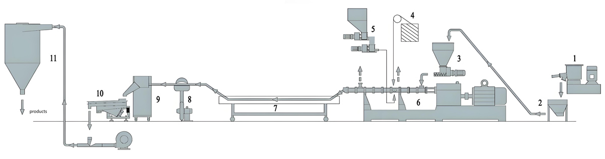
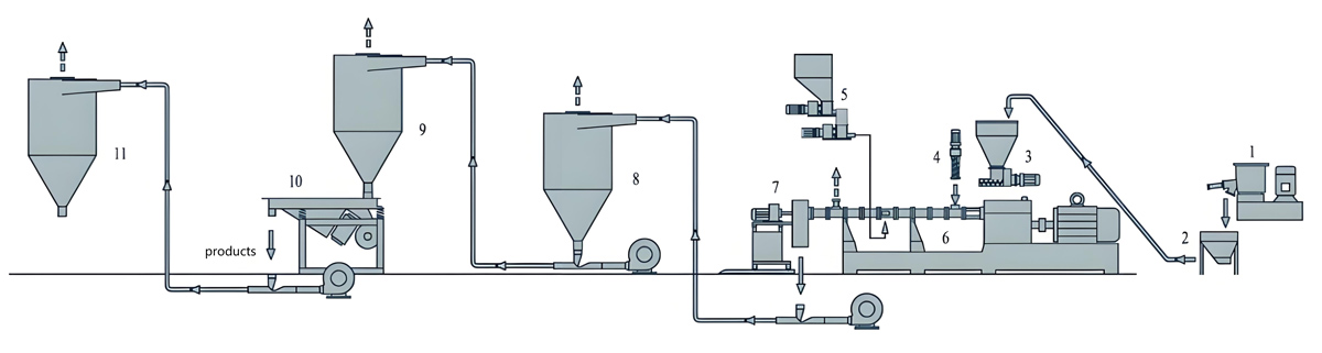
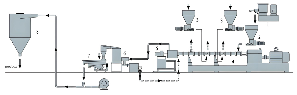
PSU masterbatch production follows a systematic process designed to handle material characteristics while ensuring consistent product quality. Each production stage requires careful attention to detail to maintain quality and processing efficiency.
Raw material preparation represents a critical first stage in PSU masterbatch manufacturing. PSU resin must be pre-dried to moisture content below 0.015% prior to processing to prevent hydrolysis during high-temperature processing. Drying typically occurs at 140-160°C for 4-6 hours depending on material form and dryer capacity. Color pigments, fibers, and additives similarly require appropriate drying or dehumidification to prevent moisture-related processing issues. Pre-blending of components using high-shear mixers ensures uniform distribution before entering the extruder, preventing segregation and ensuring consistent masterbatch quality throughout production runs.
Feeding systems for PSU masterbatch must handle diverse component types including bulk PSU pellets, fine powders, fibrous materials, and liquid additives. Gravimetric feeding systems provide precise metering of individual components, enabling accurate formulation control and consistent product quality. Multiple feed ports positioned along the extruder barrel allow staged addition of components, optimizing dispersion and processing efficiency. Liquid additives may be injected through specialized ports with appropriate metering systems. Feed system reliability directly impacts formulation accuracy, product consistency, and production efficiency, making robust feeding equipment essential for PSU masterbatch production.
Compounding in the twin screw extruder represents the core processing stage where components undergo melting, dispersion, and homogenization. The touch screen control system enables precise temperature control across heating zones, typically 280-360°C depending on formulation requirements. Screw configuration must be optimized for specific formulations, with appropriate distributive and dispersive mixing elements ensuring uniform component dispersion without excessive shear that could degrade sensitive additives. Residence time typically ranges from 1-2.5 minutes depending on material throughput and screw configuration, with appropriate length-to-diameter ratios (typically 30:1 to 36:1) providing sufficient mixing and residence time.
Venting and degassing remove volatiles and entrained gases generated during high-temperature processing. Vacuum venting systems operating at 80-150 mbar absolute pressure remove decomposition products and moisture that could cause defects in final products. Multiple vent ports positioned along the barrel remove volatiles at appropriate stages, preventing bubble formation and ensuring product quality. Proper venting prevents porosity, surface defects, and performance degradation in final applications. Vacuum pump capacity must be sized appropriately for the extruder throughput and material characteristics.
Die design for PSU masterbatch must accommodate high processing temperatures while maintaining appropriate pressure and flow characteristics. Strand dies with multiple orifices (typically 4-6 strands) provide appropriate throughput for granulation systems. Die land length and orifice diameter must be optimized for specific formulations and processing conditions. Die temperature control maintains appropriate melt temperature and prevents material degradation. Die heating systems typically use cartridge heaters with independent zone control, enabling precise temperature regulation across the die face.
Pelletizing systems for PSU masterbatch must handle high-temperature strands efficiently while producing uniform pellets. Strand pelletizing with water cooling represents the most common approach, with water bath temperature controlled at 35-50°C depending on material characteristics. Strand breakers and pelletizers cut cooled strands to uniform dimensions, typically 2-3mm length for convenient handling and processing. Alternative pelletizing methods including underwater pelletizing or face pelletizing may be used depending on specific formulation characteristics and product requirements. Pellet size uniformity, absence of fines, and consistent shape are critical quality parameters affecting downstream processing performance.
Cooling and packaging complete the production process. Pellets may undergo additional cooling or post-treatment depending on formulation requirements. Screening removes oversized or undersized pellets, ensuring product uniformity. Packaging systems provide moisture protection and convenient handling, typically in moisture-barrier bags with desiccant for hygroscopic formulations. Proper labeling including formulation codes, batch numbers, and production dates ensures traceability and quality control throughout the supply chain.
Production Equipment Description
Kerke KTE Series twin screw extruders with touch screen control systems represent industry standard for high-performance engineering plastic compounding including PSU masterbatch manufacturing. These machines provide the temperature control, processing stability, and operational control necessary for demanding PSU applications.
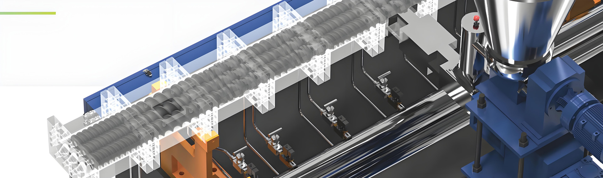
The KTE Series extruders feature advanced barrel construction with individual heating zones providing precise temperature control across the barrel length. Barrel L/D ratios range from 30:1 to 36:1, providing appropriate residence time for complete mixing and dispersion. Barrel heating utilizes high-performance ceramic band heaters providing rapid heating response and uniform heat distribution. The touch screen control system enables independent zone temperature control with ±1°C tolerance, critical for maintaining consistent processing conditions for temperature-sensitive PSU formulations. Cooling fans on barrel zones provide rapid cooling capabilities during shutdown or material transitions.
Twin screw configurations for PSU masterbatch typically employ co-rotating intermeshing screws with diameters ranging from 20mm to 75mm depending on throughput requirements. Screw elements include conveying elements for material transport, kneading blocks for distributive mixing, and special mixing elements for dispersive mixing. Screw profiles must be optimized for specific formulations, with appropriate element selection and arrangement ensuring adequate dispersion without excessive shear that could degrade heat-sensitive additives. Modular screw design allows easy configuration changes for different formulations, providing production flexibility. High-torque gearbox systems provide necessary power for processing high-viscosity PSU melts.
The touch screen control system represents a key feature of KTE Series extruders, providing comprehensive process monitoring and control capabilities. The control system typically features a 10-15 inch color touchscreen display with intuitive graphical interface. Operators can monitor and adjust multiple process parameters including individual zone temperatures, screw speed, feed rates, motor load, vacuum pressure, and melt pressure. Recipe storage systems enable rapid changeover between different formulations, storing up to 200+ production recipes. Data logging capabilities record processing parameters for quality documentation and process optimization. Alarm systems provide notification of processing excursions requiring operator attention.
Drive systems for PSU masterbatch production require substantial power to process high-temperature materials with appropriate viscosity. Motors ranging from 18kW to 300kW provide adequate power depending on extruder size and throughput requirements. Variable frequency drives allow speed adjustment across typical operating ranges of 150-400 RPM, enabling optimization for different formulations and throughput requirements. Drive systems incorporate overload protection and monitoring systems to prevent damage during processing upsets. Advanced drive controls provide integrated motor speed control with feed rate synchronization, enabling consistent formulation control and processing stability.
Feeding systems for PSU masterbatch must handle diverse material types and provide precise metering. Gravimetric feeders with individual hopper scales for each component enable accurate formulation control. Feed screw designs accommodate different material types, from free-flowing pellets to cohesive powders and fibrous materials. Feeder hopper capacities range from 40L to 800L depending on production scale and component characteristics. Feed rate control through integrated touch screen control systems synchronizes multiple feeders, maintaining consistent formulation ratios throughout production runs. Liquid addition systems with precision metering pumps enable incorporation of liquid additives with appropriate mixing and dispersion.
Vent systems for PSU masterbatch remove volatiles and moisture generated during processing. Atmospheric vents remove initial volatiles, while vacuum vents operating at 80-150 mbar remove decomposition products and moisture. Vent ports include appropriate filtration to prevent material entrainment in vacuum systems. Vacuum pump capacities range from 80 to 400 m3/h depending on extruder size and material characteristics. Condensers prevent volatile components from reaching vacuum pumps, extending pump life and reducing maintenance requirements. The touch screen control system provides vacuum monitoring and control, enabling operators to optimize degassing performance.
Die and pelletizing systems for PSU masterbatch accommodate high-temperature processing while producing uniform pellets. Strand dies with 4-6 orifices provide appropriate throughput, with die diameters typically 2-5mm depending on production rate. Die heating systems provide independent zone control across the die face, maintaining appropriate melt temperature and preventing degradation. Strand cooling baths provide controlled cooling with temperature regulation between 35-50°C. Strand breakers and pelletizers cut cooled strands to uniform lengths, with cutting speed adjustable to match extrusion rate. Pellet size control systems ensure consistent pellet dimensions.
Parameter Settings
Optimizing processing parameters for PSU masterbatch requires systematic attention to multiple variables affecting product quality, processing efficiency, and equipment reliability. Proper parameter settings depend on specific formulation characteristics, equipment capabilities, and production throughput requirements.
Temperature profile settings for PSU masterbatch typically begin with a feed zone temperature of 260-280°C, gradually increasing through compression and metering zones to peak temperatures of 340-360°C. The die zone temperature typically matches the peak barrel temperature to maintain appropriate melt viscosity for smooth extrusion. Individual zone temperatures must be optimized based on screw configuration and formulation requirements. The touch screen control system enables precise temperature control within ±1°C tolerance, critical for maintaining consistent processing conditions. Temperature profile optimization typically involves iterative adjustment based on melt temperature measurements, product quality assessment, and processing stability evaluation.
Screw speed settings directly affect residence time, shear conditions, and throughput. For PSU masterbatch, typical screw speeds range from 200-350 RPM depending on extruder size and formulation characteristics. Higher screw speeds increase throughput but reduce residence time and increase shear, potentially affecting dispersion quality and additive stability. Lower speeds provide longer residence time for better dispersion but reduce productivity. Optimal screw speed must balance throughput requirements, dispersion needs, and additive thermal stability. The touch screen control system allows precise screw speed adjustment, with display of current speed, motor load, and throughput calculations.
Feed rate settings determine material throughput and must be synchronized with screw speed to maintain appropriate fill ratio and processing conditions. Feed rates typically range from 50-400 kg/h depending on extruder size and formulation characteristics. Gravimetric feeding systems provide precise control of individual component feed rates, ensuring accurate formulation ratios. Feed rate to screw speed ratio typically maintained between 0.6-1.0 kg/h/RPM depending on screw configuration and material characteristics. Feed rate stability directly affects processing consistency, making reliable feeder performance essential for quality PSU masterbatch production.
Vacuum level settings for degassing systems typically operate between 80-150 mbar absolute pressure. Higher vacuum levels improve volatile removal but increase material entrainment risk and pump wear. Lower vacuum levels reduce material loss but may not remove all volatiles, potentially causing product defects. Optimal vacuum level depends on material volatility, throughput, and desired product quality. The touch screen control system provides real-time vacuum monitoring and control, enabling operators to optimize degassing performance. Vacuum pump capacity must be adequate to maintain desired vacuum level throughout production.
Melt pressure monitoring provides insight into processing conditions and product quality. Typical melt pressures for PSU masterbatch range from 80-150 bar depending on formulation and processing parameters. Pressure monitoring along the barrel length can identify processing problems including inadequate mixing, material degradation, or die blockage. Melt pressure transducers positioned at strategic locations provide valuable diagnostic information displayed on the touch screen interface. Pressure trends provide early warning of processing excursions requiring operator attention or automatic control system adjustment.
Throughput optimization involves balancing multiple parameters to achieve maximum production rate while maintaining product quality and processing stability. Higher throughput requires increased screw speed, feed rate, and potentially adjusted temperature profiles. Throughput increases may be limited by motor capacity, screw design, or thermal management capabilities. The touch screen control system enables monitoring of throughput calculations and equipment loading, facilitating optimization while preventing overloading. Optimal throughput depends on market demand, production scheduling, and equipment capabilities.
Equipment Pricing
Investment in touch screen control twin screw extruders for PSU masterbatch production reflects the specialized requirements of high-performance engineering plastic processing. Understanding equipment cost structure supports informed investment decisions and financial planning.
Touch screen control twin screw extruder pricing for PSU applications varies based on machine size, configuration, and control system sophistication. Entry-level systems with 20mm screws and basic touch screen control typically cost $70,000-100,000. Mid-range production systems with 40-50mm screws and comprehensive control features typically range from $200,000-320,000. Large production systems with 70mm+ screws and advanced control capabilities can exceed $500,000. Price variations reflect differences in screw configuration quality, control system sophistication, feeding system complexity, and included ancillary equipment. Kerke KTE Series systems represent premium equipment pricing reflecting advanced engineering, touch screen control capabilities, and reliability features essential for demanding PSU applications.
Touch screen control system costs vary based on display size, functionality, and integration capabilities. Basic control systems with 10-inch displays and standard functionality typically cost $15,000-25,000. Advanced control systems with 15-inch displays, recipe storage for 200+ formulations, advanced data logging, and integration capabilities with plant MES systems can cost $35,000-55,000. The control system investment provides returns through improved process control, reduced operator errors, enhanced production efficiency, and comprehensive quality documentation capabilities.
Feeding system costs depend on number of components, feeder types, and control integration. Gravimetric feeding systems for 3-4 components typically cost $25,000-40,000. Complex feeding systems handling 6+ components including liquids and various material forms can exceed $80,000. Feeder precision, capacity, and control integration features significantly affect pricing. Investment in high-quality feeding systems provides returns through improved formulation accuracy, reduced material waste, and enhanced product consistency.
Pelletizing system costs depend on throughput requirements and system sophistication. Basic strand pelletizing systems typically cost $18,000-30,000. Advanced pelletizing systems with automated strand handling, size control, and integrated drying can cost $40,000-65,000. Underwater pelletizing systems for specialized applications can exceed $100,000. Pelletizing system selection should match production requirements, product quality specifications, and available facility infrastructure.
Total system investment for complete PSU masterbatch production line typically ranges from $150,000 for basic small-scale operations to over $900,000 for large-scale automated facilities. Production capacity, automation level, and equipment quality preferences significantly affect total investment. Financial analysis should consider production volume projections, product pricing, and operating costs to determine appropriate investment level and expected return on investment.
Production Problems, Solutions, and Prevention
PSU masterbatch production presents various processing challenges that can affect product quality, production efficiency, and equipment reliability. Understanding potential problems, their causes, appropriate solutions, and prevention methods enables proactive process management.
Material Degradation and Discoloration
Material degradation during PSU masterbatch production manifests as discoloration, molecular weight reduction, gel formation, or performance degradation. Degradation causes include excessive processing temperatures, extended residence times, thermal hot spots in the barrel or die, or contamination with degrading substances. Degraded material may exhibit yellowing or darkening coloration, reduced mechanical properties, or processing difficulties.
Solutions for material degradation begin with immediate temperature reduction to appropriate processing ranges. The touch screen control system enables rapid temperature adjustment across all zones. Temperature profiling through the control interface identifies hot spots requiring adjustment. Screw configuration modification reduces excessive shear and residence time. Contaminated material sources must be identified and eliminated. Cleaning procedures remove degraded material from the equipment. Process parameters including screw speed, feed rate, and temperature profile are optimized for specific formulations.
Prevention of material degradation requires proper equipment design and maintenance. Precise temperature control through the touch screen system prevents thermal hot spots and maintains uniform temperature. Regular temperature sensor calibration ensures accurate temperature control. Screw configuration optimization prevents excessive shear. Feed system maintenance prevents contamination. Material quality testing verifies thermal stability. Process monitoring through the touch screen interface provides early warning of degradation conditions. Standard operating procedures defined in the control system memory establish appropriate processing parameters for each formulation.
Inadequate Component Dispersion
Inadequate component dispersion results in non-uniform color distribution, weak mechanical properties, or inconsistent performance in final applications. Dispersion problems manifest as pigment streaks, fiber agglomerates, or filler clustering. Causes include insufficient mixing energy, inappropriate screw configuration, inadequate residence time, or feeding problems causing component segregation.
Solutions for dispersion problems involve immediate parameter adjustment and equipment modification. Screw speed increase provides additional mixing energy, provided thermal stability considerations permit. Temperature profile adjustment improves melt viscosity and mixing capability. Screw configuration modification adds mixing elements or adjusts element arrangement. Feed system adjustment ensures proper component feeding and prevents segregation. Processing slowdown increases residence time for improved dispersion. Quality control testing verifies dispersion improvement through appropriate analytical methods.
Prevention of dispersion problems begins with appropriate screw configuration design. Screw profiles must include adequate distributive and dispersive mixing elements for specific formulations. Processing parameters optimized for each formulation balance dispersion requirements with thermal stability needs. Feed system design prevents component segregation and ensures consistent feeding. Regular equipment maintenance ensures mixing elements remain effective. Process development includes dispersion evaluation as a critical quality parameter. The touch screen control system stores optimized parameters for each formulation ensuring consistent dispersion.
Venting Problems and Porosity
Venting problems cause porosity, bubbles, or surface defects in masterbatch pellets. Causes include inadequate vacuum level, vent blockage, excessive throughput, or material generating excessive volatiles. Porosity manifests as visible bubbles in pellets or internal voids detected during downstream processing.
Solutions for venting problems include immediate vacuum level verification and adjustment through the touch screen interface. Blocked vents require cleaning to restore functionality. Throughput reduction may be necessary if venting capacity is exceeded. Temperature profile adjustment reduces thermal degradation and volatile generation. Vent location optimization removes volatiles at appropriate processing stages. Product quality testing verifies porosity elimination and product quality improvement.
Prevention of venting problems requires appropriate vent system design for expected throughput and material characteristics. Regular vent maintenance prevents blockage and ensures proper function. Processing parameters optimized to minimize volatile generation while maintaining product quality. Material selection includes consideration of volatile content and thermal stability. Monitoring vacuum levels through the touch screen control system provides early warning of developing problems. Standard operating procedures defined in recipe storage establish appropriate venting parameters for each formulation.
Die Blockage and Extrusion Instability
Die blockage causes extrusion rate variations, pressure spikes, and potential equipment damage. Causes include material degradation in the die, contaminant accumulation, inappropriate die temperature, or formulation changes causing processing difficulties. Die blockage manifests as pressure increase, rate reduction, or complete flow stoppage.
Solutions for die blockage involve immediate temperature increase to melt blockage material. Pressure relief through venting may be necessary. Die disassembly and cleaning removes blockage material. Processing parameters adjustment prevents recurrence of blockage conditions. Formulation review identifies problematic components or ratios. Equipment inspection identifies contributing factors including inadequate heating or cooling.
Prevention of die blockage requires appropriate die design and temperature control for specific formulations. Regular die cleaning prevents contaminant accumulation. Temperature monitoring through the touch screen control system ensures proper die heating. Formulation development includes die flow characteristics evaluation. Processing parameters maintain appropriate melt viscosity and temperature. Material quality control prevents contamination. Standard operating procedures include die inspection and maintenance schedules.
Feeding Problems and Formulation Inaccuracy
Feeding problems cause formulation inaccuracy, product inconsistency, and quality issues. Causes include feeder malfunction, material bridging in hoppers, component segregation, or inappropriate feeder design for specific material characteristics. Feeding problems manifest as product property variations, color inconsistency, or downstream processing difficulties.
Solutions for feeding problems involve immediate feeder verification and recalibration. Bridging material requires agitation or hopper design modification. Segregated components require improved pre-blending or feeder configuration changes. Feeder maintenance repairs mechanical problems. Process parameter adjustment may compensate for minor feeding variations. Product quality testing verifies formulation accuracy restoration. The touch screen control system provides real-time feeder monitoring and alarm functions.
Prevention of feeding problems requires appropriate feeder selection for specific material types and throughput requirements. Regular feeder calibration ensures accurate metering. Hopper design prevents material bridging and segregation. Pre-blending systems ensure uniform component distribution. Feed system monitoring through the touch screen interface provides early warning of feeding problems. Material handling procedures prevent contamination and maintain material quality. Standard operating procedures include feeder maintenance and calibration schedules.
Control System and Operator Errors
Control system and operator errors cause processing excursions, quality variations, and production inefficiencies. Causes include incorrect parameter selection, improper recipe loading, inadequate operator training, or control system malfunction. Control system errors manifest as parameter drift, incorrect processing conditions, or quality inconsistencies.
Solutions for control system errors involve immediate verification of selected recipe and parameters. Control system diagnostics identify malfunctioning components. Operator training ensures proper system usage. Recipe verification prevents incorrect parameter loading. Process parameter adjustment through the touch screen interface corrects processing conditions. Product quality testing verifies quality restoration.
Prevention of control system errors requires comprehensive operator training on touch screen control system usage. Recipe management systems prevent incorrect parameter loading through standardized recipes. Operator authentication prevents unauthorized changes. Regular system testing ensures proper function. Standard operating procedures documented in the control system guide operators through correct procedures. Alarm and interlock systems prevent inappropriate parameter combinations.
Maintenance and Upkeep
Regular maintenance ensures reliable equipment performance, extends equipment service life, and prevents costly downtime. PSU masterbatch production equipment maintenance encompasses daily, weekly, monthly, and annual activities.
Daily maintenance activities focus on immediate operational status and early problem detection. Visual inspection identifies obvious problems including leaks, unusual vibrations, or abnormal sounds. Temperature and pressure readings verification confirms normal operating conditions through the touch screen interface. Feed rate verification ensures accurate metering. Material hopper inspection confirms adequate material supply and prevents bridging. Vacuum system verification ensures proper degassing performance. Production quality control testing confirms product quality and provides early warning of processing problems. Daily maintenance log documentation records all observations and activities.
Weekly maintenance activities address routine maintenance requiring periodic attention. Feeder calibration ensures accurate metering for each component. Vent port inspection and cleaning prevents blockage and maintains vacuum system performance. Die inspection identifies contamination or wear requiring attention. Material handling system verification ensures reliable material delivery to the extruder. Control system verification confirms proper parameter settings and alarm functionality. Touch screen interface inspection ensures proper display and control response.
Monthly maintenance activities address more extensive inspection and maintenance requirements. Screw and barrel inspection identifies wear patterns requiring attention. Gearbox inspection identifies potential problems including oil degradation or gear wear. Motor inspection verifies electrical performance and mounting integrity. Heating element verification ensures proper operation and identifies failed elements. Cooling system inspection verifies proper function. Vacuum pump inspection identifies maintenance requirements. Complete system performance verification through the touch screen control system confirms overall equipment capability.
Annual maintenance activities address comprehensive inspection and maintenance requiring extended downtime. Complete disassembly inspection identifies wear and maintenance requirements throughout the equipment. Screw and barrel replacement or reconditioning addresses wear affecting performance. Gearbox rebuild or replacement addresses wear or performance degradation. Motor and drive system maintenance ensures reliable operation. Electrical system inspection and testing verifies wiring integrity and component functionality. Control system calibration ensures accurate parameter control. Touch screen system testing verifies all display and control functions. Safety system verification ensures proper operation and compliance with safety requirements.
Preventive maintenance schedules based on manufacturer recommendations and operating experience prevent failures and extend equipment life. Maintenance interval optimization balances maintenance frequency, cost, and failure risk. Spare parts inventory planning ensures critical components are available when needed. Maintenance documentation provided through the touch screen system provides complete equipment history supporting informed maintenance decisions. Maintenance personnel training ensures proper procedures and safety practices. Condition monitoring including performance trending through the control system provides early warning of developing problems.
Frequently Asked Questions
What advantages do touch screen control systems provide for PSU masterbatch production?
Touch screen control systems provide intuitive user interfaces enabling operators to monitor multiple process parameters simultaneously. The systems offer real-time monitoring of temperature profiles, screw speed, feed rates, motor load, and other critical parameters. Recipe storage enables rapid changeover between different formulations with consistent parameter settings. Data logging capabilities provide comprehensive quality documentation and process optimization support. Alarm systems provide early notification of processing excursions requiring attention. These capabilities significantly improve process control, reduce operator errors, and enhance production efficiency for PSU masterbatch manufacturing.
What throughput rates are achievable with PSU masterbatch production lines?
Throughput rates depend on extruder size, screw configuration, and specific formulation characteristics. Small 20mm extruders typically achieve 8-25 kg/h throughput. Mid-size 40-50mm extruders can process 80-250 kg/h. Large 70mm+ extruders achieve 350-600 kg/h or more. Actual throughput depends on formulation complexity, dispersion requirements, and processing parameters. The touch screen control system enables optimization of throughput while maintaining quality. Throughput optimization involves balancing production rate requirements with product quality specifications and equipment capabilities.
How do I select appropriate screw configuration for different PSU masterbatch formulations?
Screw configuration selection must account for material characteristics including viscosity, thermal sensitivity, and dispersion requirements. Formulations requiring intensive dispersion need additional kneading blocks and mixing elements. Thermally sensitive formulations require minimized residence time and shear. Fiber-reinforced formulations require gentle conveying to prevent fiber damage. Modular screw design enables configuration optimization for different formulations. Screw configuration development typically involves iterative testing and adjustment based on product quality evaluation and processing performance assessment. The touch screen control system stores optimized screw configurations for each formulation.
What are typical maintenance requirements for touch screen control systems?
Touch screen control systems require regular maintenance to ensure reliable operation. Daily maintenance includes visual inspection of the display and control panel functionality. Weekly maintenance includes verification of alarm functions and sensor responses. Monthly maintenance includes calibration of temperature sensors and verification of data logging functions. Annual maintenance includes complete system testing, software updates, and verification of all control functions. Control system documentation provided through the touch screen interface supports maintenance activities. Regular maintenance ensures accurate control and prevents control system failures affecting production.
How do I ensure consistent product quality across production batches?
Consistent product quality requires systematic process control and quality monitoring. Precise temperature control through the touch screen system ensures consistent processing conditions. Gravimetric feeding provides accurate formulation control. Process parameter monitoring through the control interface identifies variations requiring attention. Quality control testing at appropriate intervals verifies product characteristics. Statistical process control identifies trends requiring preventive action. Standard operating procedures stored in recipe memory ensure consistent processing approaches for each formulation. Material quality control prevents material-related quality variations. Regular equipment maintenance ensures consistent performance.
What are typical operating costs for PSU masterbatch production?
Operating costs for PSU masterbatch production include energy consumption, labor, materials, maintenance, and consumables. Electricity consumption depends on extruder size and throughput, typically representing 60-70% of variable operating costs. Labor costs depend on automation level and operator requirements. Material costs include PSU base material and additives, representing 75-85% of total production costs. Maintenance typically costs 2-3% of equipment investment annually. Total operating costs typically range $2.50-4.00 per kg depending on formulation complexity and production scale. The touch screen control system enables optimization of processing parameters to minimize energy consumption and improve efficiency.
Conclusion and Recommendations
PSU masterbatch production using touch screen control twin screw extruders represents a sophisticated manufacturing process requiring specialized equipment, precise process control, and comprehensive operational expertise. Investment in Kerke KTE Series extruders with advanced touch screen control systems provides appropriate temperature control, processing stability, and operational control capabilities required for demanding high-performance applications in aerospace, automotive, medical, and electronics industries.
Successful PSU masterbatch manufacturing requires systematic attention to formulation development, process optimization, equipment maintenance, and quality control. Investment in touch screen control systems provides foundation for consistent quality and efficient operation. Process parameter optimization based on specific formulation characteristics ensures product quality while maximizing production efficiency. Regular maintenance prevents costly downtime and extends equipment service life. Comprehensive quality control ensures consistent product meeting customer specifications.
Market opportunities for PSU masterbatch continue expanding as industries demand increasingly sophisticated material solutions. Manufacturers investing in appropriate touch screen control equipment and developing necessary technical expertise can capture value in this high-performance market segment. Success requires understanding of both technical challenges and market opportunities, with appropriate investment balancing production capabilities with market demand projections.