The aerospace industry demands materials that can withstand extreme conditions while maintaining exceptional mechanical properties. High strength masterbatch manufactured through advanced twin screw extrusion technology has become essential for producing composite materials that meet the rigorous standards of aerospace applications. This comprehensive guide explores the technical aspects, production methodologies, equipment selection, and operational best practices for manufacturing aerospace grade high strength masterbatch using twin screw extruders.
Introduction
Aerospace applications require polymer composites with superior strength-to-weight ratios, excellent fatigue resistance, and consistent mechanical performance under fluctuating temperatures and stress conditions. Traditional manufacturing methods often fall short in achieving the precise formulation control and homogeneous dispersion required for these demanding applications.
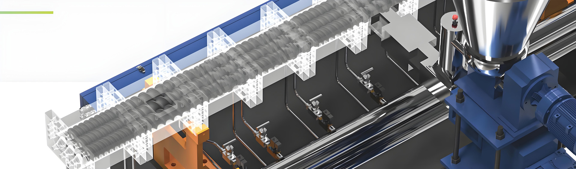
Twin screw extrusion technology has emerged as the preferred manufacturing method for producing aerospace grade high strength masterbatch. The co-rotating twin screw design enables superior mixing efficiency, precise temperature control, and consistent throughput that are critical for achieving the mechanical properties required in aerospace components.
The global aerospace materials market continues to expand as aircraft manufacturers seek lightweight solutions to improve fuel efficiency while maintaining structural integrity. This growth has driven significant advancements in masterbatch formulations and extrusion equipment capabilities.
Understanding Aerospace Grade Requirements
Aerospace grade high strength masterbatch must meet stringent specifications that differ substantially from standard industrial applications. These requirements include consistent fiber reinforcement distribution, precise additive concentration control, and minimal contamination levels throughout the production process.
The masterbatch serves as a concentrated carrier for high performance additives including carbon fiber, aramid fiber, glass fiber, and various strengthening agents. These concentrated formulations are then let down into base polymers at specified ratios to achieve the final composite material properties required for specific aerospace components.
Formulation Ratio for Aerospace Grade High Strength Masterbatch
Carbon Fiber Reinforced Masterbatch
Carbon fiber reinforced masterbatch represents the premium tier of aerospace materials. The formulation requires careful balancing of fiber content, coupling agents, and carrier resin properties to achieve optimal mechanical performance.
Typical formulation ratio for carbon fiber reinforced masterbatch includes 30 to 50 percent carbon fiber content by weight, with the remaining composition allocated to carrier resin (40-55 percent), coupling agents (2-5 percent), and processing aids (1-3 percent). The carrier resin selection depends on the target matrix polymer, with polyamide, polycarbonate, and polyetheretherketone being common choices for aerospace applications.
The carbon fiber length distribution significantly impacts the final composite properties. Optimal formulations maintain fiber lengths between 3 and 12 millimeters within the masterbatch to ensure adequate reinforcement when subsequently compounded into the final polymer matrix.
Aramid Fiber Reinforced Masterbatch
Aramid fiber reinforced masterbatch offers excellent impact resistance and thermal stability, making it suitable for aerospace components requiring damage tolerance. Formulation ratios typically range from 20 to 40 percent aramid fiber content.
The carrier system for aramid fiber masterbatch requires specialized surface treatment to ensure proper fiber-matrix adhesion. Typical formulations include 35 to 50 percent compatible carrier resin, 20 to 40 percent aramid fiber, 3 to 6 percent coupling agent system, and processing modifiers to facilitate fiber dispersion.
Glass Fiber Reinforced Masterbatch
Glass fiber remains a cost-effective reinforcement option for aerospace applications where extreme strength-to-weight ratios are not the primary concern. Formulations typically contain 30 to 60 percent E-glass or S-glass fiber content.
The formulation must account for glass fiber compatibility with various matrix systems. Coupling agents, typically silane-based, constitute 1 to 3 percent of the formulation to ensure adequate interfacial bonding between the glass fibers and polymer matrix.
Hybrid Reinforcement Masterbatch
Advanced aerospace applications increasingly utilize hybrid reinforcement systems that combine multiple fiber types to achieve balanced property profiles. These formulations require sophisticated process control to ensure uniform fiber distribution throughout the carrier matrix.
Typical hybrid formulations combine carbon fiber (15-25 percent), glass fiber (15-25 percent), and supplementary strength enhancers within a carefully selected carrier resin system. The interaction between different reinforcement types must be carefully characterized to achieve consistent performance.
Production Process for Aerospace Grade High Strength Masterbatch
Raw Material Preparation
The production process begins with meticulous raw material preparation. Carbon fibers or other reinforcement materials must be properly sized and treated to ensure compatibility with the carrier resin system. Surface treatment processes modify the fiber surface energy to promote better interfacial bonding with the polymer matrix.
Carrier resin granules are dried according to manufacturer specifications, typically requiring moisture levels below 0.02 percent for hygroscopic polymers such as polyamide. Inadequate drying results in hydrolysis during extrusion and compromised mechanical properties in the final masterbatch.
Reinforcement fibers undergo chopping or milling to achieve the target length distribution. Fiber length control during this stage directly impacts the reinforcement efficiency in final applications. Specialized equipment ensures consistent fiber length distribution without excessive fiber breakage.
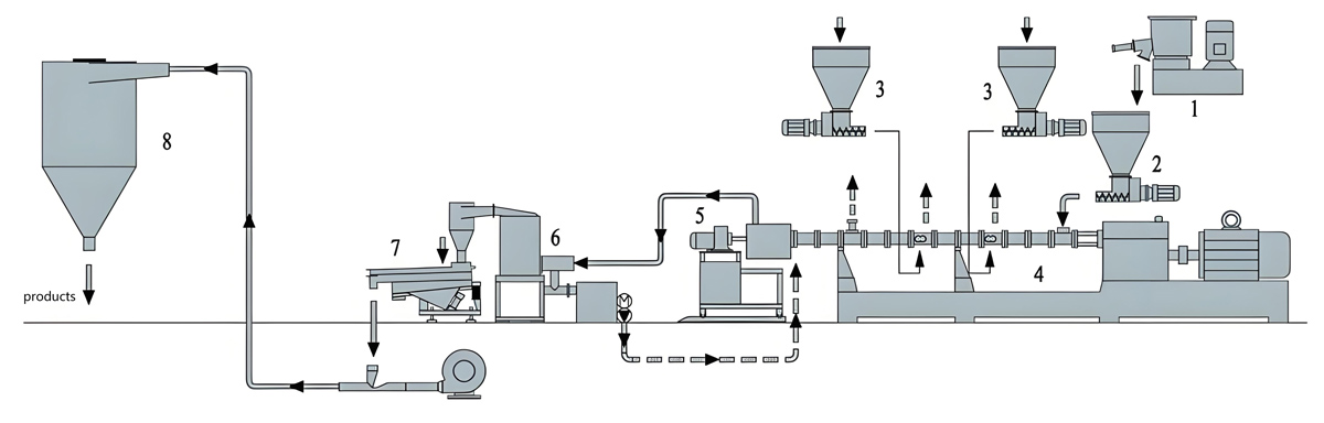
Pre-mixing and Feeding
Precise pre-mixing of formulation components ensures uniform additive distribution before extrusion. Gravimetric feeding systems provide accurate component introduction rates that maintain consistent formulation ratios throughout the production run.
The feeding system configuration depends on the specific formulation requirements. Side feeders introduce reinforcement fibers at appropriate points along the extruder barrel to minimize fiber breakage while ensuring adequate dispersion. Main feed hoppers handle carrier resin and minor additives with precise gravimetric control.
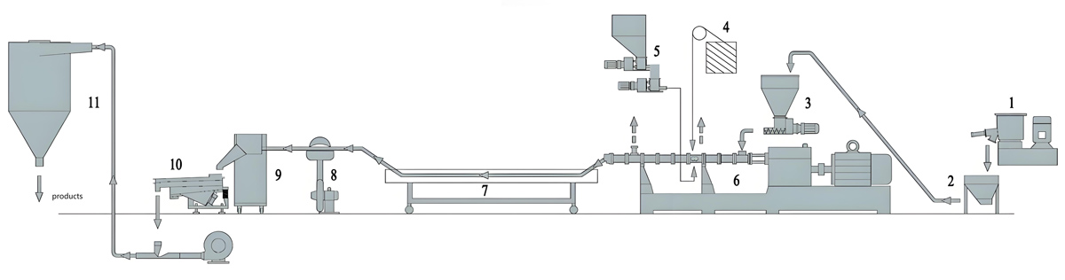
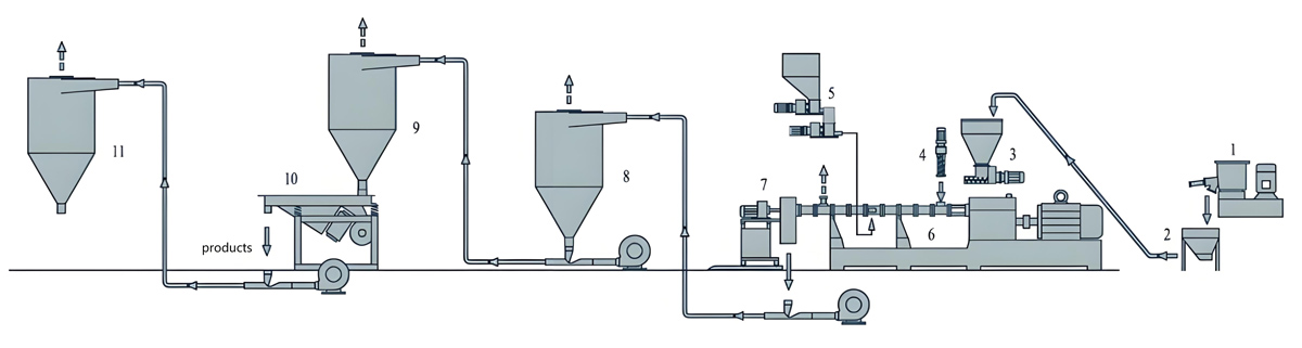
Twin Screw Extrusion Process
The twin screw extrusion process comprises several distinct zones that perform specific functions in transforming raw materials into homogeneous masterbatch. Understanding these zones enables optimal equipment configuration and process optimization.
The feeding zone accepts raw materials and begins the melting and initial mixing process. Barrel temperature in this zone is set slightly below the melting point of the carrier resin to facilitate controlled melting while preventing premature degradation of heat-sensitive additives.
The mixing zones provide the high shear forces necessary for fiber dispersion and distribution. Screw elements in these sections feature specialized designs that fold, divide, and recombine the polymer melt while introducing reinforcement fibers through side feeder ports. The intensity of mixing must be carefully controlled to achieve uniform fiber distribution without excessive fiber length reduction.
The pumping zone maintains consistent throughput while developing sufficient pressure for die extrusion. This zone requires screw elements that provide uniform delivery without additional mixing to prevent fiber degradation and ensure stable pressure profiles.
Pelletizing and Cooling
Underwater pelletizing systems provide the most consistent masterbatch pellet geometry for aerospace applications. This method produces spherical pellets with uniform size distribution that offer advantages in subsequent let-down operations and ensure consistent additive distribution in final compounds.
Water temperature control during pelletizing influences the crystalline structure of semi-crystalline carrier resins. Controlled cooling profiles can optimize carrier resin properties to enhance overall masterbatch performance.
Pellet drying follows the pelletizing process to remove surface moisture before packaging. Extended drying may be required for hygroscopic carrier resins to prevent moisture-related quality issues during storage and subsequent processing.
Production Equipment Introduction
Kerke KTE Series Twin Screw Extruders
Kerke KTE series twin screw extruders represent advanced manufacturing equipment specifically designed for high performance masterbatch production. The series encompasses multiple models optimized for different production capacity requirements.
The KTE-36B extruder features a screw diameter of 35.6mm and delivers throughput rates of 20 to 100kg per hour. This compact machine suits research and development applications as well as small volume specialty production runs. The precision engineering of this model enables excellent mixing performance despite its smaller capacity.
The KTE-50B extruder provides screw diameter of 50.5mm with throughput capabilities of 80 to 200kg per hour. This mid-range model balances production efficiency with the precise control required for aerospace grade masterbatch manufacturing.
The KTE-65B extruder offers 62.4mm screw diameter and production rates of 200 to 450kg per hour. This capacity range suits commercial production operations requiring consistent quality at moderate throughput levels.
The KTE-75B extruder features 71mm screw diameter with throughput rates of 300 to 800kg per hour. This high capacity model maintains mixing quality while enabling significant production volumes for established aerospace material suppliers.
The KTE-95D extruder provides the largest capacity in the series with 93mm screw diameter and throughput of 1000 to 2000kg per hour. This industrial scale machine meets the demands of high volume aerospace material production while maintaining the quality standards required for critical applications.
Feeding and Handling Equipment
Gravimetric feeding systems provide the precise ingredient introduction rates essential for aerospace grade formulations. These systems incorporate multiple feed hoppers with load cell based weight measurement to maintain formulation accuracy throughout production runs.
Side feeder equipment enables controlled introduction of reinforcement fibers at specific barrel locations. The side feeder design must provide sufficient capacity for high fiber feed rates while maintaining consistent fiber introduction without compaction or damage.
Material handling systems transport raw materials from storage to feeding equipment and transfer finished masterbatch to packaging or storage systems. These systems incorporate metal detection and separation equipment to prevent contamination with metallic particles that would compromise aerospace component quality.
Pelletizing and Downstream Equipment
Underwater pelletizing systems provide the preferred method for aerospace grade masterbatch production. These systems produce pellets with controlled geometry and minimal fines while enabling high production rates.
Centrifugal dryers separate pellets from cooling water with minimal mechanical stress that could damage pellets or generate fines. Integrated screens remove undersized particles to ensure consistent product quality.
Metal detection systems positioned at multiple points throughout the production line identify and remove any contaminated product. These systems achieve detection sensitivity suitable for aerospace applications where contamination tolerance approaches zero.
Parameter Settings for Aerospace Grade High Strength Masterbatch
Temperature Profile Configuration
Temperature profile settings significantly impact masterbatch quality and production efficiency. The profile must facilitate complete polymer melting while preventing thermal degradation of sensitive additives and reinforcement fibers.
Typical temperature profile for carbon fiber reinforced masterbatch using polyamide carrier begins at 220 to 240 degrees Celsius in the feeding zone, increases to 260 to 280 degrees through mixing sections, and maintains 250 to 270 degrees in the pumping and die zones. The specific profile depends on carrier resin grade, fiber content, and additive package sensitivity.
Temperature deviations from optimal profiles manifest as quality issues including incomplete fiber wetting, thermal degradation of additives, or inadequate melt viscosity for proper mixing. Regular temperature profile optimization based on product quality feedback ensures consistent production quality.
Screw Speed and Throughput Control
Screw speed influences mixing intensity, fiber attrition, and melt temperature development. Higher screw speeds increase shear rates and mixing efficiency but also increase fiber breakage and potentially generate excessive melt temperatures.
Optimal screw speeds for aerospace grade masterbatch typically range from 200 to 500 revolutions per minute depending on formulation requirements and equipment configuration. The specific speed must balance mixing requirements against fiber length retention objectives.
Throughput rates must correlate with screw speed to maintain appropriate fill level within the extruder. Insufficient fill results in poor mixing quality while excessive fill generates pressure instability and quality variation. Closed loop control systems maintain optimal fill levels through coordinated speed and feed rate adjustment.
Pressure and Vacuum Settings
Barrel pressure profiles influence mixing efficiency and volatile removal. Vent zones incorporating vacuum assistance remove moisture and volatile byproducts that could compromise masterbatch quality or create voids in subsequent processing.
Die pressure monitoring provides valuable feedback regarding melt homogeneity and potential contamination. Sudden pressure changes often indicate formulation inconsistencies or equipment issues requiring immediate attention.
Vacuum levels of 50 to 100 millibars effectively remove volatiles without excessive polymer loss through the vent system. Excessive vacuum can draw fine additive particles from the melt, creating formulation variation and potentially damaging vacuum equipment.
Residence Time Distribution
Residence time within the extruder must be sufficient for complete melting, additive dissolution, and fiber wet-out while avoiding excessive thermal exposure. Narrow residence time distribution improves product consistency by ensuring all material receives similar processing.
Mean residence times for aerospace grade masterbatch typically range from 30 to 90 seconds depending on formulation complexity and required mixing intensity. Process validation studies establish the residence time requirements for specific formulations.
Screw design optimization can narrow residence time distribution and improve product consistency. Barrier elements and pumping screws create more uniform flow patterns that reduce product quality variation.
Equipment Price
Equipment investment for aerospace grade high strength masterbatch production requires careful evaluation of production capacity requirements and quality standards. The Kerke KTE series offers multiple configurations to address different production scales and budget constraints.
The KTE-36B twin screw extruder represents the entry point for aerospace grade masterbatch production at a price range of $25,000 to $35,000. This investment provides research and development capability and small volume production capacity. The compact design enables installation in facilities with limited space while maintaining the quality standards essential for aerospace applications.
The KTE-50B twin screw extruder price ranges from $40,000 to $60,000, representing a mid-range investment for growing production requirements. This capacity level supports pilot production and initial commercial quantities while maintaining the precision necessary for aerospace quality standards.
The KTE-65B twin screw extruder requires an investment of $50,000 to $80,000. This model addresses production requirements for established suppliers serving aerospace industry customers with moderate volume requirements.
The KTE-75B twin screw extruder commands a price range of $70,000 to $100,000, reflecting its higher production capacity and robust construction for demanding aerospace applications. This investment suits dedicated aerospace material production facilities.
The KTE-95D twin screw extruder represents the premium equipment tier with prices ranging from $120,000 to $200,000. This industrial scale machine enables high volume production while maintaining the precision and quality consistency required for aerospace applications.
Complete production line investment extends beyond the extruder itself to include feeding systems, pelletizing equipment, material handling, quality control instrumentation, and facility modifications. Total system investments typically range from 1.5 to 3 times the extruder purchase price depending on automation levels and quality system requirements.
Problems in Production Process and Solutions
Poor Fiber Dispersion and Distribution
Problem Description: Inadequate fiber dispersion manifests as visible fiber bundles, uneven mechanical properties, and inconsistent color in finished masterbatch. This issue typically emerges from insufficient mixing energy, improper screw configuration, or inadequate pre-mixing of formulation components.
Root Cause Analysis: The mixing zones may lack sufficient shear intensity to separate fiber bundles and distribute individual fibers throughout the polymer matrix. Feed rate variations can create local areas of excessive or insufficient mixing. Temperature variations cause viscosity differences that impair mixing efficiency in specific barrel sections.
Solution Approach: Modify screw configuration to increase mixing element density in problem areas. Adjust temperature profiles to achieve uniform melt viscosity throughout the mixing zones. Implement gravimetric feeding to eliminate feed rate variations that create inconsistent mixing conditions. Consider adding pre-mixing equipment to ensure uniform additive distribution before extrusion.
Prevention Methods: Establish standard screw configurations for specific formulation types based on accumulated process knowledge. Implement statistical process control on feed rates and temperature profiles to identify drift before quality problems emerge. Conduct regular mixing efficiency validation using sampling and analysis protocols.
Excessive Fiber Length Reduction
Problem Description: Fiber length reduction beyond design specifications compromises reinforcement efficiency in final applications. This manifests as lower than expected tensile strength, impact resistance, or stiffness in composites produced with the masterbatch.
Root Cause Analysis: High shear screw elements, excessive screw speed, and extended residence time all contribute to fiber breakage. Improper feeding techniques that subject fibers to pre-mature mechanical stress before reaching the extruder can also cause length reduction.
Solution Approach: Optimize screw speed to balance mixing requirements against fiber attrition. Review screw element selection to identify high shear elements that may be unnecessary for the specific formulation. Modify feeding configurations to minimize fiber stress before entering the extruder barrel.
Prevention Methods: Establish fiber length specifications and testing protocols for each masterbatch formulation. Monitor fiber length trends over time to identify equipment or process changes that affect fiber integrity. Document optimal processing parameters for each formulation to ensure repeatability.
Moisture Related Defects
Problem Description: Moisture contamination produces surface imperfections, reduced mechanical properties, and processing problems in subsequent applications. These defects often manifest as bubbles, voids, or reduced tensile strength in finished products.
Root Cause Analysis: Inadequate drying of hygroscopic carrier resins before extrusion allows moisture to vaporize during processing, creating voids and surface defects. Moisture can also react with certain polymers during extrusion, causing chain scission and property degradation.
Solution Approach: Verify dryer performance through regular moisture content testing of dried materials. Extend drying times or increase drying temperatures for problematic materials. Consider implementing desiccant drying systems that achieve lower moisture levels for highly sensitive polymers.
Prevention Methods: Establish comprehensive drying protocols for each raw material based on supplier recommendations and validation testing. Implement incoming material moisture testing to identify batches requiring extended drying. Maintain drying equipment according to manufacturer schedules to ensure reliable performance.
Inconsistent Color and Appearance
Problem Description: Color variation between production batches or within individual batches creates quality issues for aerospace components where appearance specifications may apply. This problem also indicates potential formulation inconsistency that could affect functional properties.
Root Cause Analysis: Poor dispersion of colorants or additive settling during production can create color variation. Inconsistent feed rates for minor additives cause formulation variations that affect color. Contamination from previous production runs may introduce color bodies into subsequent production.
Solution Approach: Implement stringent cleaning procedures between production runs of different formulations. Verify feeding system accuracy and cleanliness before production starts. Adjust mixing intensity or residence time to improve additive dispersion.
Prevention Methods: Establish cleaning validation protocols that specify procedures for different formulation transitions. Implement production scheduling that minimizes problematic formulation changes. Conduct regular feeding system calibration and maintenance.
Die Plate Fouling and Blockage
Problem Description: Accumulation of polymer degradation products or additive agglomerates on die plate surfaces creates flow restrictions and pressure variations. This manifests as production rate variations and potential quality issues from localized overheating.
Root Cause Analysis: Thermal degradation of polymer or additives at die plate surfaces creates carbonaceous deposits over time. High concentration of certain additives can cause agglomeration that builds up on flow restricting surfaces.
Solution Approach: Implement regular die plate cleaning schedules based on production experience. Adjust temperature profiles to minimize thermal exposure at die plate locations. Consider filter elements to capture agglomerates before they reach die plate surfaces.
Prevention Methods: Monitor pressure trends at die locations to identify fouling before significant accumulation occurs. Establish preventive maintenance schedules for die plate inspection and cleaning. Optimize formulations to minimize components prone to thermal degradation.
Maintenance
Daily Maintenance Procedures
Daily maintenance activities establish the foundation for reliable equipment operation and consistent product quality. Operators should inspect feeding equipment for proper function and material flow before each production shift. Verification of feeding system calibration ensures continued formulation accuracy throughout production.
Barrel temperature profile verification identifies any heating element or sensor failures that could create quality problems. Recording actual temperatures against setpoints enables trend analysis that identifies developing problems before they cause quality failures.
Die plate inspection and cleaning removes accumulated material that could restrict flow or create contamination. Visual inspection of pellets produced during startup identifies any quality issues requiring immediate attention.
Equipment cleanliness inspection verifies that material spills and dust accumulation are controlled to prevent contamination events. Immediate cleanup of any spills prevents cross-contamination between production runs.
Weekly Maintenance Procedures
Weekly maintenance extends beyond daily activities to address components requiring less frequent attention. Screw element torque indicator inspection identifies any loosening that could allow element rotation during operation. Torque measurements provide baseline data for detecting changes over time.
Feeding system calibration verification using test weights confirms continued accuracy of gravimetric feeding systems. Any deviations from expected accuracy require investigation and correction before production continues.
Die plate and transition piece inspection examines wear patterns and accumulated deposits that may not be addressed in daily cleaning. Detailed inspection records enable prediction of maintenance requirements and scheduling of replacement before failures occur.
Vacuum system inspection and cleaning maintains effective volatile removal capability. Filter inspection and replacement prevents vacuum system performance degradation that could allow volatiles to remain in the product.
Monthly and Quarterly Maintenance
Monthly maintenance addresses components that require periodic attention to maintain performance standards. Barrel and screw wear inspection identifies sections requiring replacement due to erosion or wear patterns. Early identification enables scheduled replacement during planned downtime rather than emergency repairs.
Gearbox oil analysis and replacement maintains mechanical transmission health. Oil analysis provides advance warning of contamination or degradation that could lead to equipment failure if not addressed.
Electrical system inspection examines connections, motor condition, and control system calibration. Temperature controller calibration verification ensures accurate temperature measurement and control throughout the barrel profile.
Quarterly maintenance includes comprehensive equipment inspection that addresses all major systems. Extruder barrel inspection using borescope equipment identifies internal wear patterns and accumulated deposits that affect product quality. Documentation of findings enables long term trend analysis and capital planning for equipment replacement.
Annual Maintenance and Calibration
Annual maintenance represents comprehensive equipment overhaul that ensures continued reliability and quality performance. Complete extruder disassembly and inspection examines all internal components for wear, damage, or accumulated material that could affect performance.
Screw element replacement planning considers accumulated operating hours and historical wear patterns to identify optimal replacement schedules. Proactive replacement of worn elements prevents quality problems that emerge from excessive wear.
Control system calibration and software updates ensure continued accurate equipment operation. Backup of all process parameters and formulations enables rapid recovery in case of control system failure.
Performance qualification testing verifies equipment capability to produce product meeting specifications. Documentation of qualification results provides evidence of continued equipment capability for quality system purposes.
FAQ
What are the critical quality specifications for aerospace grade high strength masterbatch?
Aerospace grade masterbatch must meet stringent specifications including consistent fiber content within tight tolerances, defined fiber length distribution, absence of contamination above specified limits, and reproducible mechanical properties when compounded into final products. Each aerospace customer typically defines specific requirements based on their application needs and regulatory compliance requirements.
How do I select the appropriate KTE model for my production requirements?
Model selection depends on required production volume, formulation complexity, and quality standards. The KTE-36B suits research and development and small volume specialty production. The KTE-50B and KTE-65B address moderate commercial production requirements. The KTE-75B and KTE-95D serve high volume production operations with established aerospace customer bases. Consulting with Kerke technical specialists helps match equipment specifications to specific application requirements.
What carrier resins are suitable for aerospace grade masterbatch?
Common carrier resins include polyamide for general purpose applications, polycarbonate for optical and structural uses, polyetheretherketone for extreme temperature applications, and polypropylene for cost-sensitive applications. The carrier must be compatible with both the reinforcement fibers and the target matrix polymer used in final composite production.
How do I prevent fiber breakage during extrusion?
Fiber breakage prevention requires balancing mixing intensity against processing conditions. Optimize screw speed to minimize unnecessary shear. Configure screw elements to provide adequate mixing without excessive stress on fibers. Ensure proper feeding techniques that minimize fiber stress before entering the extruder. Validate fiber length in finished product to confirm that processing conditions maintain target lengths.
What quality control tests should I implement for aerospace applications?
Essential quality control tests include fiber content determination, fiber length distribution analysis, mechanical property testing of compounded samples, moisture content verification, contamination screening, and color consistency measurement. Statistical process control on critical parameters ensures consistent quality across production batches. Many aerospace customers require specific qualification testing protocols that must be documented and followed.
How often should I perform equipment maintenance?
Maintenance frequency depends on production volume and operating conditions. Daily activities include visual inspection and temperature verification. Weekly activities address feeding system calibration and die maintenance. Monthly activities include wear inspection and oil analysis. Annual maintenance encompasses comprehensive equipment overhaul and performance qualification. Documenting all maintenance activities creates records essential for quality system compliance and equipment reliability optimization.
Can I produce multiple formulations on the same equipment?
Multiple formulation production on shared equipment is possible with appropriate cleaning procedures between production runs. The cleaning protocol intensity depends on formulation differences and contamination sensitivity. Some formulations may require extensive cleaning to remove traces that could affect subsequent products. Planning production sequences to minimize problematic transitions reduces cleaning requirements and changeover time.
What are the typical production rates for different KTE models?
Production rates vary with formulation and operating conditions. The KTE-36B produces 20 to 100kg per hour. The KTE-50B produces 80 to 200kg per hour. The KTE-65B produces 200 to 450kg per hour. The KTE-75B produces 300 to 800kg per hour. The KTE-95D produces 1000 to 2000kg per hour. Actual rates depend on formulation density, required mixing intensity, and specific product quality requirements.
Conclusion
Manufacturing aerospace grade high strength masterbatch using twin screw extrusion technology requires careful attention to formulation design, process optimization, equipment selection, and quality management. The Kerke KTE series provides equipment solutions ranging from research scale to industrial production that meet the demanding requirements of aerospace applications.
Successful production of aerospace grade masterbatch depends on understanding the relationships between formulation variables, processing conditions, and final product properties. Investment in process knowledge development, quality systems, and equipment maintenance yields returns through consistent product quality and reduced production problems.
The aerospace industry continues to drive demand for advanced materials that improve aircraft performance while maintaining safety standards. Twin screw extrusion technology provides the capability to produce these materials consistently and efficiently, supporting the continued growth of aerospace applications worldwide.
Organizations entering the aerospace grade masterbatch market must recognize that quality system requirements extend beyond product specifications to encompass documentation, traceability, and process control capabilities that satisfy aerospace customer expectations. Investment in these capabilities positions manufacturers to capture opportunities in this demanding but rewarding market segment.
The technical knowledge presented in this guide provides a foundation for developing aerospace grade masterbatch manufacturing capabilities. Ongoing process optimization, equipment maintenance, and quality system refinement will establish operational excellence that differentiates successful manufacturers in the competitive aerospace materials market.