Introduction
Glass fiber filled masterbatch production is a technically demanding segment of plastic compounding that provides significant mechanical property improvements including tensile strength, modulus, and dimensional stability. Glass fibers are particularly valuable in applications requiring lightweight reinforcement to replace traditional materials like metal or wood. Twin screw extruders have become the preferred processing equipment for glass fiber masterbatch production due to their precise control capabilities and ability to handle abrasive materials while minimizing fiber breakage.
Glass fiber filler masterbatch typically contains 20-40% glass fiber, depending on application requirements and fiber type. The material is used extensively in automotive components, electrical enclosures, construction materials, and consumer goods where strength-to-weight ratio is critical. Glass fiber masterbatch provides substantial stiffness improvement and heat deflection temperature enhancement while maintaining relatively low density compared to filled alternatives like talc or calcium carbonate.
The production of high-quality glass fiber masterbatch requires specialized formulation design and processing optimization to achieve uniform fiber dispersion while preserving fiber length, which significantly affects final mechanical properties. Excessive shear during processing breaks fibers into shorter pieces, reducing reinforcement effectiveness. Process conditions must balance effective fiber wetting and distribution with fiber length preservation.
This comprehensive guide explores glass fiber filled masterbatch production technology, from formulation principles and fiber selection criteria to processing optimization and quality assurance. It addresses technical challenges of high fiber loading, dispersion quality, and length preservation. By understanding critical factors affecting glass fiber performance and available processing technology, manufacturers can produce high-quality glass fiber masterbatch that meets demanding application requirements.
Formulation Proportions (Different Types)
Glass fiber filled masterbatch formulation varies significantly based on application requirements, fiber type, and desired performance properties. Basic formulation principles involve balancing fiber loading with matrix polymer type, coupling agent level, and processing aids to achieve optimal product properties while maintaining processability.
General Purpose Formulation
For general purpose applications requiring good stiffness improvement and dimensional stability, formulation consists of 25-35% glass fiber, 60-70% carrier polymer, 0.5-2% coupling agent, and 0.5-1% processing aid. The exact proportions depend on fiber type and length.
A typical general purpose formulation uses 30% chopped glass fiber, 67% polypropylene carrier, 2% silane coupling agent, and 1% polyethylene wax processing aid. This formulation provides excellent reinforcement and good processability in polypropylene applications.
For polyethylene applications, formulation adjusts accordingly to use compatible coupling agents and processing aids. Typical proportions are 25% glass fiber, 72% HDPE carrier, 2% titanate coupling agent, and 1% PE wax processing aid. This maintains good dispersion quality while optimizing mechanical properties in PE systems.
Carrier polymer selection depends on intended use. For engineering applications, the corresponding engineering polymer or functionalized polymer compatibilizer ensures proper fiber-matrix adhesion. Compatibilizer addition may be required for enhanced mechanical properties in specific applications.
High Strength Formulation
For applications requiring maximum strength improvement, high strength formulations contain 35-40% glass fiber with specialized coupling agent systems. These formulations require optimized formulation and processing conditions to maintain acceptable dispersion quality without excessive fiber breakage.
A high strength formulation consists of 38% continuous glass fiber strands, 59% carrier polymer, 2.5% dual coupling agent system (silane and titanate), and 0.5% flow improver. The continuous fiber bundles provide maximum reinforcement before undergoing shearing during extrusion.
For short fiber formulations with high loading (35-40%), specialized processing aids including viscosity modifiers and mold release agents are necessary to maintain processability under high shear conditions. Customized dispersant systems with dual action lubrication and coupling properties improve mixing efficiency while minimizing fiber damage.
High strength formulations may use reinforcing agents including glass microspheres or microfibers in combination with traditional fibers to improve mechanical properties further. These hybrid formulations offer balanced properties including high strength, low shrinkage, and improved surface finish.
Electrical Application Formulation
Electrical applications require glass fiber masterbatch meeting specific performance standards including dielectric strength, arc resistance, and low moisture absorption. Specialized additives including insulation enhancers and flame retardants may be incorporated depending on specific electrical requirements.
A typical electrical formulation consists of 20-30% glass fiber as reinforcement filler, 65-75% carrier polymer (typically PP or PET), 1-3% coupling agent, and 2-5% performance additives depending on specific electrical application needs.
For electrical enclosures requiring good insulation performance, formulation may consist of 25% glass fiber, 72% PP carrier, 2% silane coupling agent, 0.5% flame retardant, and 0.5% UV stabilizer. This provides necessary reinforcement while meeting electrical component standards for insulation and flame resistance.
For printed circuit board applications requiring high dimensional stability, glass fiber loading may be increased to 30-35% to enhance stiffness and reduce warpage during soldering operations. High-temperature polymers like PBT or PET may replace standard polyolefins for improved thermal resistance.
Hybrid Formulation
Hybrid formulations combine glass fiber with other fillers including mineral fillers or carbon fibers to achieve balanced properties. The hybrid approach optimizes different reinforcement mechanisms to achieve desired mechanical properties or cost targets.
A typical hybrid formulation consists of 20% glass fiber, 15% talc filler, 62% carrier polymer, 2% coupling agent, and 1% processing aid. The combination provides synergistic effects: glass fiber offers high tensile strength while talc enhances dimensional stability and surface smoothness.
For cost-sensitive applications, hybrid formulations may contain 10% glass fiber and 25% calcium carbonate filler to reduce material cost compared to 35% pure glass fiber formulation while providing reasonable property improvements compared to unfilled polymer.
Carbon fiber hybrid formulations for high-performance applications typically contain 10-20% carbon fiber with complementary 10-15% glass fiber. Carbon fiber provides excellent stiffness-to-weight ratio, while glass fiber improves impact resistance and reduces material cost compared to pure carbon fiber formulations.
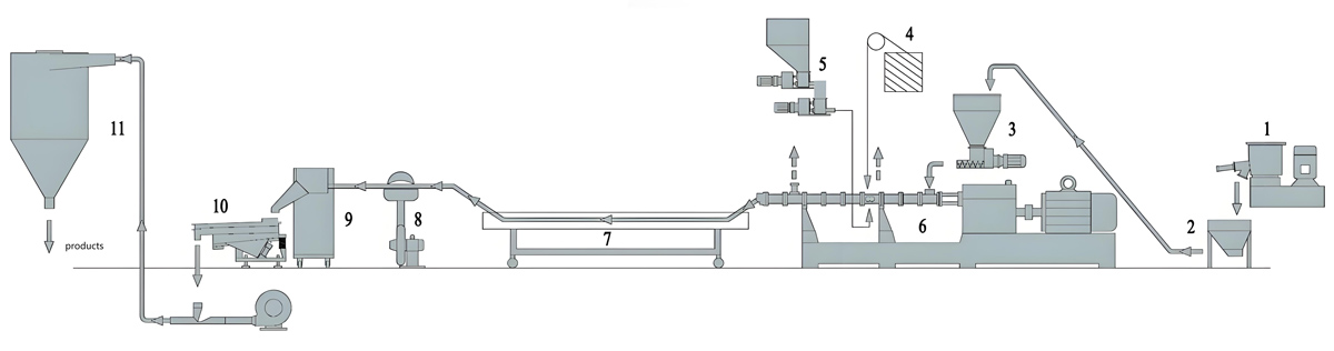
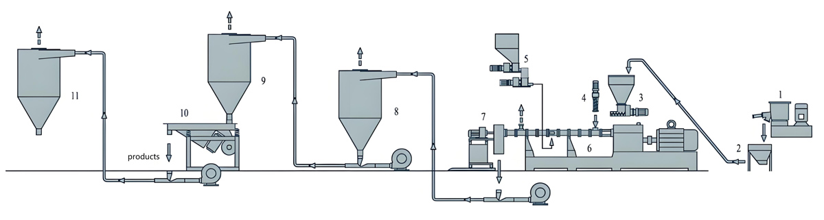
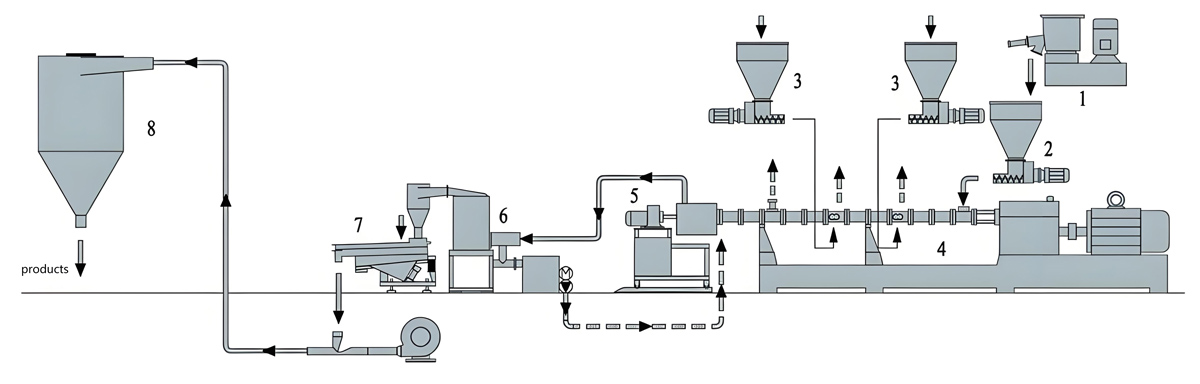
Production Process
Glass fiber filled masterbatch production follows systematic processes requiring precise control at each stage to ensure consistent quality while preserving fiber length. Production begins with raw material preparation and ends with final quality verification before shipment.
Raw Material Preparation
Raw material preparation involves careful handling and conditioning of incoming materials to ensure consistency and quality. Glass fiber must be tested for fiber length distribution, surface treatment effectiveness, moisture content, and sizing quality.
Moisture content should be reduced below 0.1% using dehumidifying dryers to prevent moisture-related processing issues during extrusion. Moisture above this level can cause hydrolysis of sizing chemicals and coupling agents, reducing fiber-matrix bonding effectiveness.
Carrier polymers require melt flow index verification to ensure consistent processing characteristics. Virgin polymer is typically used, though specific applications may allow limited recycled content provided mechanical property requirements allow it.
All additives including coupling agents and processing aids must be examined for purity and performance compatibility. Silane coupling agents should be tested for hydrolytic stability and effectiveness under processing conditions.
Formulation Preparation
Formulation preparation involves precise weighing and batching according to formulation specifications. Automated batching systems provide accuracy and consistency required for high fiber loading formulations with critical coupling agent ratios.
For high fiber loading formulations requiring precise component proportioning (±0.2%), gravimetric batching systems are strongly recommended. Batch records should document all raw material lot numbers, weights, and batching parameters for complete traceability.
Pre-mixing should generally be avoided for glass fiber formulations to prevent fiber breakage during mixing operations. Separated feeding systems ensure gentle fiber introduction to prevent premature fiber damage before entering extrusion melt zone.
Material transfer systems must prevent fiber damage during handling operations. Gentle conveying systems reduce mechanical stress on fibers, preserving fiber length before processing.
Twin Screw Extrusion Process
The extrusion process for glass fiber filled masterbatch requires optimizing processing parameters to achieve uniform fiber dispersion while preserving fiber length. The twin screw extruder provides precise process control essential for balancing dispersion effectiveness and fiber length preservation.
Feed system design is critical for glass fiber processing. Side feeding technology is strongly recommended to introduce fibers downstream after polymer melting zone, minimizing fiber residence time and reducing shear exposure that could break fibers.
Extrusion temperature profile must be optimized for specific formulation components, balancing complete polymer melting with coupling agent stability. Typical temperature profile starts at 170-190°C in feed zone, increasing to 200-220°C in compression zones, and 210-225°C at die for polypropylene-based formulations.
Screw configuration should minimize shear stress while providing adequate mixing for good dispersion. KTE Series twin screw extruder includes specialized low-shear mixing elements optimized for glass fiber processing applications to preserve fiber length.
Pelletizing Process
Pelletizing converts extrudate into uniform granules suitable for downstream processing. Strand pelletizing is commonly used due to simplicity and cost-effectiveness, though underwater pelletizing provides advantages in preserving fiber orientation.
Strand pelletizing involves passing extrudate through a cooling water bath to solidify strands before cutting into pellets. The water temperature should be maintained between 20-30°C to achieve proper cooling without causing thermal shock that could affect polymer-fiber bonding.
Underwater pelletizing processes strands under water immediately after exiting die. This prevents fiber orientation in specific directions and produces spherical pellets with more uniform mechanical properties in all directions.
Pellet size should be controlled between 2-3mm diameter to ensure good flow and feeding characteristics in downstream processing applications. Cutter blade maintenance and adjustment are critical for maintaining consistent pellet dimensions while minimizing fiber damage.
Quality Control and Testing
Comprehensive quality control protocols ensure consistent product quality and customer satisfaction. Testing includes visual inspection, fiber length measurement, mechanical property evaluation, and dispersion quality assessment.
Fiber length analysis using optical microscopy determines average fiber length distribution after processing. Preserving length above 0.5mm is critical for maintaining reinforcement effectiveness in most applications.
Mechanical property testing typically includes tensile modulus, tensile strength, and impact resistance evaluation. These properties provide insight into formulation effectiveness and fiber reinforcement characteristics relative to fiber length distribution.
Dispersion quality evaluation involves microscopic examination of molded test plaques to check for uniform fiber distribution and identify agglomerate formation that could affect performance.
Chemical analysis verifies coupling agent effectiveness through testing interface bonding quality using various analytical techniques including Fourier transform infrared spectroscopy (FTIR) to confirm chemical bonding between fiber and matrix polymer.
Production Equipment Introduction
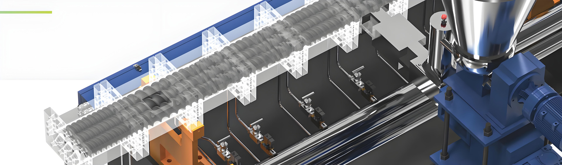
Kerke KTE Series Twin Screw Extruder
The Kerke KTE Series twin screw extruder offers advanced extrusion technology optimized for glass fiber filled masterbatch production. Specifically designed for abrasive materials requiring fiber length preservation, the KTE Series provides precise process control essential for high-quality glass fiber compounding.
The KTE Series features co-rotating twin screw design with screw diameters from 25mm to 100mm and length-to-diameter ratios from 36:1 to 48:1. This extended processing length provides sufficient residence time for thorough dispersion without excessive fiber shearing. Barrel segments incorporate precise temperature control zones with individual PID controllers to maintain uniform heat distribution.
Variable speed drive technology enables independent screw speed control from 50-600 rpm depending on machine size. The AC vector drive provides excellent torque characteristics at all speeds, allowing operators to optimize shear levels for specific fiber loading requirements while preserving fiber length.
Advanced screw configurations optimized for glass fiber compounding are available, focusing on distributive mixing rather than intensive dispersive mixing. These configurations minimize fiber shear damage while achieving uniform fiber distribution throughout polymer matrix.
Glass Fiber Feeding System
Precise feeding is critical for maintaining formulation consistency and preserving fiber length during glass fiber processing. Specialized feeding configurations are required to handle fibers gently and introduce them to melt without premature damage.
Side feeding systems with dedicated drives ensure smooth fiber introduction to molten polymer without disrupting main melt flow. Side feeding significantly reduces fiber residence time compared to main zone feeding, minimizing exposure to high shear zones that could break fibers.
Gravimetric feeding systems with loss-in-weight technology ensure accurate fiber proportioning throughout production runs. These systems provide continuous weight measurement and automatic feed rate adjustment to maintain formulation ratios even with challenging fiber flow characteristics.
Vibratory feed hoppers with level sensors ensure consistent fiber flow to extrusion feed zone while minimizing fiber damage from excessive agitation. Carefully designed hopper geometry prevents fiber bridging and ensures uniform material discharge.
For fiber bundles requiring pre-opening before feeding, specialized pneumatic systems separate fiber bundles gently without creating excessive tension that could cause breakage before entering extruder.
Precision Temperature Control
Precise temperature control is essential for glass fiber filled masterbatch production to ensure polymer melting, coupling agent activation, and dispersion quality. The KTE Series incorporates advanced temperature management systems for uniform heat distribution.
Zone-based temperature control provides individual PID regulation for each barrel section, allowing precise temperature profile optimization. Barrel heating elements use high-efficiency cartridge heaters with rapid response time, while water cooling jackets provide effective temperature regulation during start-up and shutdown cycles.
Melt temperature monitoring at strategic barrel positions ensures actual melt conditions match set points. Thermal couples placed in melt flow channels provide direct melt temperature measurement rather than relying solely on surface temperature readings.
Temperature control algorithms optimize heating and cooling cycles to minimize temperature fluctuations and ensure uniform melt conditions throughout production. Temperature limits established for each formulation prevent overheating that could affect additive stability or polymer properties.
Processing Optimization Equipment
Specialized processing optimization tools enhance glass fiber filled masterbatch production efficiency and quality. Vacuum degassing systems remove volatiles and moisture from melt, improving product quality and dimensional stability.
Melt filtration systems remove contaminants and large agglomerates that could cause downstream processing issues. Screen pack configurations must balance filtration effectiveness with pressure drop. Coarser screens (20-40 mesh) are often used to prevent excessive fiber damage while removing large inclusions.
Inline quality monitoring systems provide real-time feedback on melt characteristics and fiber distribution. Optical fiber concentration sensors measure glass fiber content continuously during production to ensure formulation consistency.
Process data collection systems store detailed production parameters for later analysis and process optimization purposes. This data helps identify correlations between processing conditions and final product fiber length and mechanical property performance.
Parameter Settings
Optimal parameter settings for glass fiber filled masterbatch production depend on formulation specifics, fiber loading, fiber type, and equipment configuration. The following sections provide general guidelines that should be adjusted based on actual production conditions.
Extrusion Parameters
Screw speed settings depend on fiber loading and length. For moderate loading formulations (25-30%), screw speeds typically range from 120-180 rpm for 50mm extruder size. Lower speeds reduce fiber breakage risk while still providing adequate mixing.
Temperature profile should be optimized to achieve adequate polymer melting while maintaining coupling agent stability. For polypropylene-based formulations, typical temperatures start at 180°C in feed zone, increase to 200°C in compression zones, 215°C in mixing zones, and 220°C at die.
Throughput rates depend on machine size and fiber loading level. A 50mm KTE Series extruder can process 70-120 kg/h with 30% glass fiber loading, depending on formulation viscosity characteristics and fiber type.
Back pressure should be maintained between 1.5-2 MPa to ensure adequate melt compression and uniform flow through die. Lower pressures may cause inconsistent pellet quality, while excessively high pressures increase shear stress and fiber breakage tendency.
Feeding Parameters
Feeding system calibration requires validation using actual glass fiber to account for specific material flow characteristics. Regular calibration checks every 80 hours of production help maintain consistent formulation ratio and prevent overfeeding.
Feeding position optimization is critical for preserving fiber length. Side feeding should occur downstream after main polymer melting zone to minimize fiber exposure to high shear in melting zone. Optimal side feeder location varies by screw configuration and formulation specifics.
Feeding rate synchronization ensures stable formulation ratio throughout production runs. Independent feed drives allow adjusting fiber feeding rate dynamically to match main polymer feed rate changes during production transitions.
Moisture control parameters include dew point level (-40°C or lower) and residence time in dryers. These parameters ensure moisture content below 0.1% to prevent coupling agent hydrolysis during processing.
Mixing System Parameters
Screw configuration should minimize shear stress while providing distributive mixing to ensure uniform fiber distribution without excessive fiber breakage. KTE Series includes specialized low-shear mixing elements for glass fiber processing.
Mixing zone location should provide sufficient residence time for wetting and distribution without prolonged shear exposure. The optimal position is typically after polymer melting but before high-shear zones that could damage fiber length.
Shear optimization involves balancing screw speed and element configuration to achieve good dispersion without creating conditions that cause excessive fiber breakage. Distributive mixing elements rather than intensive kneading blocks are preferred for glass fiber applications.
Clearance dimensions between screw elements and barrel must be maintained through regular equipment maintenance. Increased clearance reduces shear stress but may also reduce mixing effectiveness requiring parameter adjustments for consistent performance.
Equipment Price
The investment required for glass fiber filled masterbatch production depends on production scale, automation level, and quality control requirements. The following price estimates provide general guidance for various equipment configurations.
KTE Series Twin Screw Extruder Pricing
The Kerke KTE Series offers competitive pricing while maintaining high quality standards for glass fiber compounding applications. Price levels vary by machine size and configuration complexity:
KTE-25 (25mm screw diameter): $95,000 – $130,000. Laboratory/pilot-scale model suitable for formulation development and small-scale production with specialized glass fiber handling features.
KTE-40 (40mm screw diameter): $165,000 – $215,000. Mid-range production model offering capacity of 30-80 kg/h with basic process control features designed for glass fiber processing.
KTE-50 (50mm screw diameter): $240,000 – $310,000. Standard production model suitable for medium-scale glass fiber masterbatch production with advanced control systems and fiber preservation features.
KTE-75 (75mm screw diameter): $370,000 – $480,000. High-capacity production model for large-scale operations with integrated automation and specialized wear-resistant components for abrasive fiber processing.
Custom configurations with specialized quality assurance equipment and advanced length monitoring systems may increase prices by 25-35% above standard model prices.
Accessory Equipment Pricing
Essential accessory systems contribute to total investment but are critical for maintaining product quality and process efficiency:
Gravimetric glass fiber feeding system with side feeder: $35,000 – $70,000 depending on fiber type feeding requirements and automation level.
Fiber length analysis system with optical microscopy: $25,000 – $45,000 for quality control testing to verify fiber length preservation during processing.
Quality assurance laboratory equipment: $55,000 – $95,000 including tensile testing machines, impact testers, and optical microscopy for fiber quality analysis.
Automated batching system with traceability features: $40,000 – $80,000 for closed-loop formulation management and compliance documentation.
Complete glass fiber masterbatch production line with KTE-50 extruder and essential accessories: $350,000 – $460,000 installed, depending on specific configuration complexity and automation level.
Operating Cost Considerations
Beyond initial capital investment, ongoing operating costs significantly impact total cost of ownership. Key operating cost factors include raw material costs, energy consumption, maintenance expenses, and quality control costs.
Energy consumption varies by machine size and operating conditions. A KTE-50 extruder typically consumes 85-130 kW/h during production, translating to $14,000-$22,000 in annual electricity costs at typical industrial rates assuming 5000 operating hours per year.
Maintenance costs average 3-4% of equipment value annually when following preventive maintenance protocols. This includes routine inspection, wear part replacement due to fiber abrasion, control system calibration, and quality assurance equipment servicing.
Quality control costs including routine testing and process monitoring should be budgeted at 0.5-1.0% of annual sales revenue for most applications. This includes raw material inspection, in-process testing, and final product verification.
Raw material costs represent the largest variable cost component, with glass fiber typically representing 40-60% of material cost depending on fiber grade and length. Fiber selection based on type and length significantly affects material cost and final product mechanical properties.
Production Problems and Solutions
Glass fiber filled masterbatch production presents unique challenges requiring specialized troubleshooting approaches. Issues often relate to fiber breakage, dispersion quality, and final product mechanical performance properties. The following sections address common problems and recommended solutions.
Problem 1: Excessive Fiber Breakage
Excessive fiber breakage is one of the most common quality issues in glass fiber compounding. This results in shorter fiber lengths and significantly reduced mechanical property improvement potential compared to expected levels based on fiber loading.
Cause Analysis
Multiple factors can cause fiber breakage: excessive screw speed creating high shear stress, poor screw configuration with intensive mixing elements, inadequate temperature profile causing high viscosity and increased shear forces, improper feeding introducing fibers prematurely in solid zone rather than after melting, and excessive back pressure in die creating shear stress during final extrusion.
Melt temperature variation causes inconsistent viscosity, creating higher shear stress zones where fibers experience greater breakage potential. Poor temperature uniformity through barrel can cause hot spots that degrade fiber sizing chemicals affecting fiber-matrix adhesion.
Barrel and screw wear increases clearance dimensions, sometimes forcing materials through smaller gaps in other locations, creating localized high shear zones that damage fibers.
Solution
Reduce screw speed to lower shear stress while maintaining adequate mixing intensity. Gradually reduce speed until achieving balance between fiber length preservation and acceptable dispersion quality.
Revise screw configuration to replace intensive kneading blocks with more distributive mixing elements. Wider kneading blocks (3-4mm) with smaller offset angles provide mixing while minimizing fiber damage potential.
Increase extrusion temperature by 10-20°C to reduce melt viscosity and reduce shear stress on fibers during processing. Higher temperatures lower polymer chain entanglement forces allowing easier fiber movement through melt.
Optimize feeding position and fiber introduction method to melt rather than solid zone. Side feeding technology significantly reduces fiber exposure to shearing elements in main feed zone, preserving length before mixing stage.
Prevention
Implement comprehensive equipment maintenance program ensuring consistent clearance dimensions between screw elements and barrel surfaces. Regular dimensional measurement allows proactive element replacement before excessive wear causes fiber damage.
Develop fiber preservation guidelines including maximum screw speed limits based on fiber length and type. These guidelines should define acceptable speed ranges to maintain target fiber lengths after processing.
Establish temperature profile standards validated through length analysis tests to ensure thermal conditions minimize fiber breakage while allowing proper polymer melting and coupling agent activation.
Implement routine fiber length monitoring to detect developing trends requiring process adjustments. Statistical process control charts monitor average fiber length over time to identify issues early before becoming critical.
Problem 2: Poor Fiber Dispersion
Poor fiber dispersion results in visible fiber agglomerates in pellets, non-uniform mechanical properties, and reduced property improvement effectiveness. Agglomerates create stress concentration points that reduce overall material strength and increase failure risk.
Cause Analysis
Poor dispersion can result from inadequate temperature profile preventing proper fiber wetting, insufficient mixing intensity breaking apart agglomerates, incompatible coupling agent reducing fiber-polymer adhesion, improper feeding creating uneven distribution, or temperature variation causing fiber agglomeration during melt stage.
Incompatible or insufficient coupling agent allows fiber-fiber interaction rather than fiber-polymer interaction, causing agglomeration in melt. Defective sizing chemicals on fiber surface can also cause poor wetting behavior.
Low melt viscosity due to high temperature or low polymer molecular weight may cause fibers to float and agglomerate rather than distribute uniformly throughout matrix. Inadequate mixing cannot overcome high interfacial forces between fibers under poor wetting conditions.
Solution
Improve dispersion quality through processing parameter optimization. Increase temperature 10-20°C to improve fiber wetting by reducing melt viscosity and increasing molecular mobility around fibers. Improved wetting reduces interfacial forces between fibers allowing easier distribution.
Adjust screw configuration to incorporate more mixing elements if agglomeration persists despite improved wetting conditions. Wider kneading blocks with neutral conveying angles provide distributive mixing without causing excessive fiber breakage.
Increase coupling agent level or change coupling agent type to improve fiber-polymer interaction. Dual coupling systems combining silane and titanate agents may provide improved wetting in problematic formulations.
Improve feeding practices through side feeding or multi-point feeding techniques to avoid localized high fiber concentration areas that cannot disperse adequately later in processing.
Prevention
Verify fiber surface treatment quality before production through supplier documentation and chemical testing. Only fibers with intact sizing showing good polymer compatibility should be used in formulations requiring high dispersion quality.
Establish formulation guidelines correlating coupling agent level and effectiveness for specific fiber and polymer combinations. Testing different coupling agent types provides data for optimal selection for each formulation.
Implement dispersion quality monitoring through visual inspection and microscopy to detect agglomerates early. Quick formulation or process adjustments can prevent large production batches of poor-quality material.
Maintain consistent temperature control to prevent viscosity variations that could cause fiber agglomeration. Use advanced PID tuning techniques and redundant temperature sensors for reliable temperature profile maintenance.
Problem 3: Reduced Mechanical Property Improvement
Reduced mechanical property improvement compared to expected values typically indicates combined effects of fiber breakage, poor dispersion, or inadequate fiber-matrix bonding. Stiffness and strength improvements fall below benchmark levels despite specified glass fiber loading.
Cause Analysis
Multiple factors can contribute to reduced property improvement: excessive fiber breakage, poor dispersion creating stress concentrations and ineffective reinforcement, ineffective coupling agent application reducing fiber-matrix stress transfer efficiency, formulation imbalance affecting polymer-fiber interaction, and thermal degradation reducing polymer chain length during processing.
Coupling agent hydrolysis during processing from moisture or high temperature reduces chemical bonding effectiveness, limiting stress transfer potential between fiber and matrix. This results in debonding behavior at fiber-matrix interface during mechanical loading.
Processing instability leading to fiber orientation in flow direction creates anisotropic properties with strong directionality. This reduces effective property improvement in directions perpendicular to flow compared to properties measured in flow direction.
Solution
Address fiber breakage through process optimization by reducing screw speed and implementing low-shear screw configuration as described earlier. This preserves fiber length necessary for effective reinforcement.
Improve coupling agent effectiveness through process control including moisture control and proper temperature profile maintenance. Ensure proper mixing of coupling agent into melt before fiber introduction to allow chemical activation before fiber addition.
Optimize formulation ratios including coupling agent and processing aid levels based on compatibility testing. Small formulation adjustments can significantly improve property improvement potential.
Reduce extrusion temperature or introduce cooling to minimize thermal degradation risks during prolonged residence times. Adjust formulation with thermal stabilizers to improve polymer stability under processing conditions.
Prevention
Develop comprehensive property validation protocols for each formulation including baseline mechanical property tests at expected fiber lengths. This establishes performance benchmarks for quality monitoring during production.
Implement process control systems to maintain consistent extrusion parameters across production runs. Statistical analysis identifies correlations between process variations and final property outcomes.
Validate coupling agent stability under actual processing conditions through accelerated testing protocols. This ensures proper selection and application methods for effective interfacial bonding throughout production runs.
Perform regular quality audits correlating test results with final product customer feedback. This closes loop between quality testing in plant and real-world performance in applications.
Problem 4: Abrasive Wear to Equipment
Glass fiber is highly abrasive, causing accelerated wear of screw elements, barrel surfaces, and die components during processing. This increases maintenance costs and downtime while also potentially affecting processing consistency over time.
Cause Analysis
Abrasive wear occurs as hard glass particles rub against metal surfaces during extrusion, removing material over time and increasing clearance dimensions. High fiber loading and prolonged processing increase wear rate.
Inadequate lubrication from insufficient processing aids increases direct contact between glass fibers and metal surfaces accelerating wear. Poor dispersion can cause concentrated fiber flow paths that wear specific areas quickly.
Incorrect screw material selection without proper wear resistance properties also contributes to faster wear in glass fiber processing applications.
Solution
Upgrade to wear-resistant screw elements and barrel surfaces including nitride treatments, carbide coatings, or specialized wear-resistant alloys. These materials provide longer service life under abrasive conditions compared to standard materials.
Optimize processing aid level to improve lubrication and reduce direct contact between glass fibers and metal surfaces. Increased wax levels or specialized lubricants improve surface separation between glass fibers and screw elements.
Reduce screw speed and extrusion load to decrease material velocity through extruder components. Lower velocity reduces kinetic energy of abrasive particles impacting metal surfaces, slowing wear rate.
Implement redundant equipment for critical wear-prone components to allow scheduled replacement rather than emergency downtime. Planned component replacement based on wear monitoring data avoids unexpected production interruptions.
Prevention
Establish preventive maintenance program with regular dimensional inspection of screw and barrel components. Wear monitoring allows projecting remaining service life and scheduling replacements proactively.
Implement equipment usage policies separating abrasive fiber processing from sensitive material production. This reduces wear on expensive equipment that does not need exposure to abrasive conditions.
Develop maintenance standards based on production volume and fiber loading levels. Higher loads require more frequent inspections and maintenance activities to prevent unexpected failures.
Track equipment performance data correlating wear rates with process parameters to identify optimization opportunities. Statistical analysis finds operating conditions minimizing wear while maintaining product quality.
Problem 5: Processing Instability
Processing instability manifests as pressure fluctuations, temperature variations, inconsistent throughput, and final product quality fluctuations. This leads to scrap generation, increased downtime, and inconsistent product properties.
Cause Analysis
Multiple factors can cause instability: material feeding inconsistency, temperature control issues, screw wear changing process dynamics, formulation variation, and inadequate degassing removing volatiles effectively from melt.
Poor fiber feeding characteristics can cause irregular material flow, creating intermittent melt viscosity variation that disrupts process stability. Fiber bridging in hoppers or feeder jams cause irregular feeding.
Thermal variation caused by heater malfunction or improper zone temperature setting creates inconsistent viscosity leading to flow fluctuations. Inadequate cooling capacity during high load periods may cause temperature drift increasing instability.
Solution
Improve feeding reliability through gravimetric feeding systems with loss-in-weight technology providing continuous flow feedback. These systems automatically adjust feed rates to maintain consistent flow rates despite material flow variations.
Upgrade temperature control system with faster response heaters and precision temperature sensors. Implement predictive control algorithms to anticipate temperature changes and make adjustments proactively.
Optimize screw design and configuration to include pressure compensation zones that dampen pressure fluctuations. Modular screw sections allow quick replacement based on wear or process requirement changes.
Enhance degassing system performance with improved vacuum capability and barrel venting. Adequate degassing removes moisture and volatile byproducts contributing to melt instability and foaming.
Prevention
Implement preventive maintenance program including heater performance calibration and temperature sensor validation. Regular equipment checks ensure proper operation of all temperature control components.
Establish standard operating procedures for formulation changes including transition material handling to avoid feeding inconsistencies during changeover periods.
Train operators on recognizing early signs of process instability including pressure fluctuations, temperature drift, and extrudate appearance changes. Empowered operators can take quick corrective action before small issues become large problems.
Install process monitoring equipment including pressure transducers and melt pressure indicators with visual alarms providing real-time feedback about process condition stability.
Maintenance
Proper maintenance is essential for consistent production quality and maximum equipment uptime in glass fiber filled masterbatch production. Glass fiber abrasive characteristics require specialized maintenance approach focusing on wear components and process control.
Preventive Maintenance Schedule
The following maintenance schedule provides recommended intervals for glass fiber filled masterbatch production equipment. Adjustments may be needed based on specific operating conditions and formulation characteristics.
Daily Maintenance
Operators should perform routine daily checks including visual inspection of machine for leaks, unusual sounds, or vibration. Temperature and pressure gauge readings should be verified against set points and logged in batch records.
Inspect material feed system for proper operation, ensuring smooth fiber flow and no bridging in hoppers. Clean feed zones if necessary to maintain consistent material delivery to extruder.
Record production parameters including throughput, screw speed, temperatures, and energy consumption. Compare these to baseline values and investigate any significant deviations that may indicate developing problems.
Perform visual inspection of extrudate for signs of fiber agglomeration or uneven distribution that could indicate process issues needing attention.
Weekly Maintenance
Weekly maintenance includes detailed inspection of wear components including screw elements and barrel surfaces. Measure wear indicators on critical sections using precision measuring tools.
Calibrate gravimetric feeding systems using standardized weight verification procedures. Check feeder accuracy across operational range to ensure consistent formulation ratio maintenance.
Inspect temperature control systems including sensor calibration status and heater performance. Clean heating element insulation covers to maintain heat transfer efficiency and prevent overheating hazards.
Inspect vacuum degassing system performance including pump oil level and filter condition. Replace filters and perform pump maintenance according to manufacturer recommended intervals.
Monthly Maintenance
Monthly maintenance includes comprehensive inspection of drive system components including motor bearings, gearbox, and coupling condition. Check gear lubrication level and quality, replenish or change oil as needed.
Validate process control system performance through simulated process deviation tests. Verify alarm response times and safety interlock functionality according to equipment safety documentation.
Inspect quality assurance laboratory equipment including tensile testing machine calibration status and optical microscopy performance. Review analytical method documentation for ongoing compliance with quality standards.
Clean material transfer system components and perform leak testing of closed transfer lines. Verify air quality in pneumatic systems is maintained within specifications for reliable operation.
Quarterly Maintenance
Quarterly maintenance involves major wear component inspection and potential replacement. Remove screw elements and check wear patterns and dimensional accuracy using precision measurement equipment.
Perform complete electrical system safety audit including ground continuity testing, motor winding resistance measurement, and control panel enclosure integrity check according to safety standards.
Validate quality monitoring system performance through cross-checking with laboratory testing results. Verify online sensor calibration against reference standards and adjust as needed.
Review maintenance records and update preventive maintenance schedule based on observed equipment wear rates and formulation-specific operational demands. Adjust frequency based on actual performance data.
Annual Maintenance
Annual preventive maintenance includes complete machine disassembly and component inspection at major service intervals. Evaluate wear condition of screw elements, barrel liners, bearings, seals, and drive system components.
Validate calibration of all control system instruments using traceable reference standards. Document calibration records for regulatory audit purposes including instrument serial numbers, calibration dates, and adjustment history.
Perform comprehensive safety system validation including emergency stop functionality, guard interlocks, and pressure relief valve testing. Review safety documentation update status based on regulatory requirements changes.
Review complete maintenance program effectiveness and adjust based on equipment performance data. Implement continuous improvement initiatives based on downtime analysis and maintenance cost trends.
FAQ
Q1: What is the optimal glass fiber loading for mechanical property improvement?
The optimal glass fiber loading depends on application requirements and desired balance between mechanical properties and processability. For most general purpose applications, 25-30% loading provides excellent stiffness enhancement while maintaining reasonable toughness. Higher loadings up to 35-40% offer maximum stiffness improvement but require optimized formulation and processing conditions.
Property improvement reaches plateau around 35% for short fiber formulations as fiber crowding limits effective reinforcement. Economic analysis typically shows that 28-32% loading provides the best overall balance between performance improvement and cost-effectiveness.
For applications requiring minimal impact strength reduction, lower loadings (15-25%) may be necessary despite higher material cost. The balance between stiffness improvement and property requirements must be evaluated for each specific application scenario.
Q2: How does fiber length affect mechanical properties?
Fiber length significantly influences mechanical property improvement potential, with longer fibers providing more effective stress transfer than shorter fibers. Fibers must exceed critical length threshold to transfer stress effectively, typically 0.2-0.5mm for glass fiber reinforced polymers.
Tensile strength and modulus increase with fiber length up to practical limits of extrusion processing. However, fiber orientation and distribution quality become more important than length after critical length is exceeded beyond certain level.
Very long fibers (1mm+) are difficult to process without breakage during extrusion operations. Practical processing limits typically result in average lengths between 0.3-0.8mm after extrusion, depending on processing conditions and fiber type.
Short fiber formulations provide consistent performance with acceptable property improvement for many applications while offering better processability compared to long fibers. However, long fibers provide superior reinforcement for demanding structural applications requiring maximum mechanical properties.
Q3: What types of coupling agents work best for glass fiber masterbatch?
Several coupling agent types work effectively depending on polymer matrix compatibility: silane coupling agents are most common for polyolefin systems including polypropylene and polyethylene; titanate coupling agents are effective for polar polymers like PVC or PET; zirconate coupling agents provide broad compatibility across various polymer types.
Silane coupling agents contain reactive groups that bond chemically to both fiber glass surface and polymer matrix. This chemical bonding significantly improves stress transfer efficiency, enhancing mechanical properties.
For polypropylene applications, aminosilane coupling agents (A-1100 or A-1120) provide excellent adhesion through hydrogen bonding interactions. Methacryloxy silanes (A-174) improve compatibility through copolymerization with polymer matrix during processing.
Coupling agent concentration typically ranges from 0.5-2% based on fiber surface area. Higher levels provide better coverage but diminishing returns above 2%. Formulation optimization determines the optimal balance for specific application requirements.
Q4: What processing methods preserve fiber length best?
Several processing techniques minimize fiber breakage while achieving good dispersion quality: side feeding technology introducing fibers after polymer melting reduces exposure to high shear feeding zone; low shear screw configuration with wide kneading blocks provides mixing without fiber breakage; low screw speed minimizing overall shear input; adequate temperature control lowering viscosity to reduce fiber friction forces; and special processing aids to lubricate fiber surfaces reducing shear damage.
Optimal processing conditions balance between fiber length preservation and sufficient mixing for good dispersion. These require specific screw design and parameter selection tailored for glass fiber applications.
Processing parameters including screw speed, temperature, and back pressure all influence final fiber length outcome. Process optimization should prioritize fiber length for strength-critical applications while maintaining minimum quality standards.
Q5: What challenges are unique to glass fiber compounding compared to other fillers?
Glass fiber compounding presents several unique challenges: abrasive wear on equipment requiring special materials and maintenance; fiber breakage sensitivity requiring low-shear processing conditions to preserve reinforcement potential; difficulty achieving good dispersion while maintaining fiber length balance; anisotropic properties creating directional behavior due to fiber orientation during processing; and coupling agent chemistry requiring specific process conditions for effective activation and bonding.
Unlike spherical fillers like talc or calcium carbonate, glass fiber reinforcing potential depends heavily on fiber length and orientation, not just filler loading. This makes length preservation critical processing priority.
Environmental considerations include dust control for worker safety and health protection from fiber particles during transfer and processing operations. This requires specialized dust collection systems and personal protective equipment (PPE).
Recycling also presents challenges as fiber length typically cannot be restored once broken during recycling process. Recycled glass fiber reinforced material has lower property improvement potential compared to virgin material.
Q6: How do I troubleshoot inconsistent property improvement between batches?
Inconsistent property improvement requires systematic root cause analysis starting with confirming fiber length variations between batches using microscopy measurement. Statistical comparison of average lengths may identify differences requiring processing parameter adjustment.
Check coupling agent effectiveness through chemical testing or interfacial adhesion measurement. Variations in coupling agent storage, moisture absorption, or thermal degradation could reduce bonding effectiveness.
Analyze process parameter variations including temperature profile, screw speed, and feeding position consistency. Small parameter deviations can cause significant fiber length or property differences across production batches.
Examine formulation consistency including raw material changes or component ratio variations. Batch record verification can identify raw material lot changes contributing to inconsistent properties.
Q7: How do surface treatments affect glass fiber performance?
Glass fiber surface treatments significantly improve compatibility with polymer matrix through coating application that promotes fiber-matrix adhesion. Unsized glass fiber has inherently poor bonding with most polymers due to smooth glass surface and chemical incompatibility.
Typical surface treatments use silane coupling agents applied during fiber manufacturing to chemically bond with glass surface and create reactive sites for polymer interaction. These treatments improve wetting and fiber distribution in polymer melt while enhancing interfacial bonding.
Sizing agents contain combination of coupling agents, lubricants, antistatic agents, and protective chemicals to optimize handling, processing, and performance properties. Proper sizing enhances dispersion quality and fiber protection during extrusion process.
Damaged or incomplete sizing during handling can cause poor processing and property results. Maintaining proper storage conditions protects fiber surface quality before processing stage.
Q8: How can I minimize fiber orientation effects during processing?
Fiber orientation occurs during extrusion and downstream processing as fibers align with melt flow direction, creating anisotropic material properties. This causes stronger properties in flow direction compared to perpendicular directions.
Minimizing orientation can be achieved using processing techniques including increasing melt temperature to reduce viscosity and improve fiber mobility, reducing shear rate using lower screw speeds, implementing balanced melt flow designs, and using mixing elements that counteract orientation effects.
For applications requiring isotropic properties, underwater pelletizing strand before cooling can reduce orientation effects compared to strand pelletizing that encourages alignment during solidification.
Design optimization including special mixing elements and feed zone configurations can promote three-dimensional fiber orientation rather than single direction alignment. This provides more uniform material performance across all directions.
Q9: What are the effects of glass fiber on mold shrinkage?
Glass fiber incorporation significantly reduces mold shrinkage compared to unfilled polymer due to reinforcing effect limiting polymer chain mobility during cooling and crystallization phases. Typical shrinkage reduction ranges from 30-70% at 30% fiber loading compared to unfilled material.
Reduced shrinkage provides improved dimensional stability and warpage control in molded parts. However, fiber orientation during processing creates directional shrinkage differences requiring careful mold design compensation.
Glass fiber nucleation effect promotes faster polymer crystallization in semi-crystalline polymers, contributing to faster cycle times in injection molding operations despite presence of filler material.
For dimensional-critical applications, predicting shrinkage requires testing specific formulation under actual processing conditions due to directional effects. Mold shrinkage testing using standard plaque specimens provides valuable data for mold cavity sizing and design optimization.
Q10: How do I select the optimal glass fiber grade for my application?
Glass fiber grade selection involves balancing multiple factors including required mechanical properties, processing conditions, surface finish requirements, and cost considerations. Begin by defining performance requirements including tensile strength, modulus, impact strength, and dimensional stability specifications.
For general purpose automotive interior applications, chopped glass fiber (length 3-6mm) with standard E-glass chemistry provides optimal balance of performance and processability. This grade delivers required reinforcement while maintaining reasonable impact strength.
For high-performance applications requiring maximum strength-to-weight ratio, continuous glass fiber strands or long fiber pellets may be warranted despite higher processing requirements. These forms preserve longer lengths for exceptional reinforcement.
Specialty fibers including high-strength S-glass, low-alkali C-glass, or electrical-grade glass provide specific performance characteristics including increased strength, improved chemical resistance, or lower electrical conductivity for demanding applications.
Consultation with glass fiber suppliers and testing multiple grades in actual formulation and processing conditions provides the most reliable basis for optimal grade selection. Pilot-scale testing validates performance before committing to full-scale production.
Summary
Glass fiber filled masterbatch production is a technically challenging process requiring careful formulation design, processing optimization, and quality control measures. The twin screw extruder is the preferred processing equipment due to precise process control capabilities required to balance fiber dispersion and length preservation. The KTE Series twin screw extruder from Kerke Extrusion Equipment offers advanced technology specifically optimized for glass fiber compounding applications.
Formulation design involves balancing fiber loading with matrix polymer type, coupling agent level, and processing aids to achieve optimal product properties while maintaining processability. General purpose formulations typically contain 25-35% glass fiber, with variations based on specific application requirements and fiber characteristics.
Processing parameters including temperature profile, screw speed, and screw configuration must be optimized to achieve uniform fiber dispersion while preserving fiber length. Low-shear screw configuration and side feeding technology help minimize fiber damage during processing stage.
Comprehensive quality assurance programs including fiber length analysis, mechanical property testing, and dispersion quality assessment ensure consistent product quality and customer satisfaction. Regular maintenance programs addressing wear components, control system calibration, and safety equipment validation are essential for long-term equipment reliability.
By understanding critical factors affecting glass fiber performance and implementing appropriate control measures throughout production process, manufacturers can produce high-quality glass fiber masterbatch that meets demanding application requirements. This requires ongoing commitment to continuous improvement through process optimization and technological upgrades to meet evolving industry demands.
Ultimately, successful glass fiber filled masterbatch production combines advanced extrusion technology with rigorous quality management systems and technical expertise in fiber compounding applications. This enables manufacturers to establish themselves as reliable suppliers of glass fiber masterbatch products in competitive plastic compounding industry.