The manufacturing of wear-resistant and anti-scratch masterbatch represents a critical segment within the plastics industry, serving applications ranging from automotive interiors to consumer electronics housings. Twin screw extruders have emerged as the preferred equipment for producing these specialized compounds due to their superior mixing capabilities, precise temperature control, and consistent output quality. This comprehensive guide examines the complete production process for wear-resistant and anti-scratch masterbatch using twin screw extrusion technology, providing manufacturers with detailed insights into formulation development, equipment selection, parameter optimization, and quality assurance practices.
Introduction to Wear-Resistant and Anti-Scratch Masterbatch
Wear-resistant and anti-scratch masterbatch is a concentrated formulation designed to enhance the surface durability of plastic products. These additives work by creating a harder surface layer that resists abrasion, friction, and surface damage during normal use and handling. The primary active ingredients include synthetic silica particles, ceramic microspheres, polytetrafluoroethylene (PTFE) powders, and specialized surface-modified mineral fillers. When properly dispersed within the polymer matrix, these additives significantly improve the scratch resistance, Martens hardness, andTaber abrasion performance of the final plastic article.
The demand for wear-resistant masterbatch has grown substantially in recent years, driven by the automotive industry’s focus on durable interior surfaces, the consumer electronics sector’s requirement for scratch-resistant device housings, and the furniture industry’s need for long-lasting surface finishes. Manufacturers increasingly recognize that incorporating wear-resistant additives through masterbatch offers superior dispersion compared to direct addition of neat additives, resulting in more consistent product performance and improved processing characteristics.
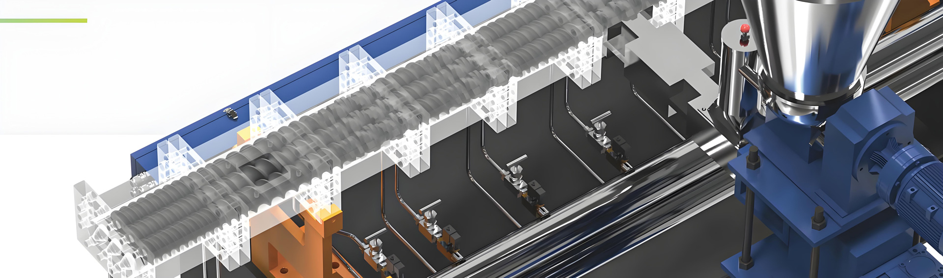
Twin screw extrusion technology provides the ideal manufacturing platform for these formulations because the co-rotating screw elements create intense distributive and dispersive mixing that breaks down agglomerates and ensures uniform distribution of hard particles throughout the polymer carrier. The modular screw configuration allows processors to customize the mixing intensity to match the specific requirements of different additive systems, from soft elastomer-based scratch resistance to ceramic-reinforced high-hardness formulations.
Formulation Ratios for Wear-Resistant and Anti-Scratch Masterbatch
The formulation of wear-resistant masterbatch varies significantly depending on the target application, performance requirements, and cost considerations. Processors must balance additive concentration against processing difficulty and final product properties when developing their formulations.
Standard Wear-Resistant Formulation
The most common formulation type uses synthetic amorphous silica as the primary active ingredient. This formulation typically contains 30 to 50 percent synthetic silica with a median particle size between 2 and 5 micrometers, 1 to 3 percent silane coupling agent for improved polymer compatibility, and the remainder consisting of carrier resin selected to match the target polymer system. The carrier resin is typically chosen from polyethylene wax, polypropylene homopolymer, or ethylene-vinyl acetate copolymer depending on the intended application and processing requirements.
For general-purpose applications such as furniture components and consumer product housings, a loading level of 35 to 40 percent synthetic silica provides adequate wear resistance while maintaining good processibility. These formulations achieve a surface hardness improvement of 15 to 25 percent compared to unfilled polymers, with Taber abrasion values typically reduced by 30 to 50 percent depending on the specific additive system and loading level.
High-Performance Ceramic-Reinforced Formulation
For applications requiring exceptional surface hardness and scratch resistance, ceramic-reinforced formulations offer superior performance characteristics. These masterbatches typically contain 25 to 40 percent alumina trihydrate or zirconia particles, 5 to 15 percent synthetic silica for synergistic reinforcement, and surface treatment agents comprising 1 to 2 percent of the total formulation. The ceramic particles provide Mohs hardness values of 8 to 9, compared to approximately 6.5 to 7 for synthetic silica, resulting in significantly improved surface protection.
The incorporation of ceramic microspheres with median diameters between 1 and 3 micrometers offers additional benefits including improved flow properties and reduced filler agglomeration tendency. These hollow or solid ceramic particles act as load-bearing elements within the polymer matrix, distributing stress concentrations and preventing surface damage from mechanical impact and abrasion.
PTFE-Enhanced Formulation
PTFE-based anti-scratch formulations provide excellent lubricity and release properties in addition to surface protection. These masterbatches typically contain 15 to 25 percent PTFE powder with particle sizes between 5 and 20 micrometers, combined with 20 to 35 percent synthetic silica or ceramic reinforcement. The PTFE component forms a low-friction surface layer that reduces scratch initiation and propagation, while the hard mineral fillers provide the primary wear resistance mechanism.
PTFE-containing masterbatches require careful processing to prevent particle agglomeration and ensure uniform dispersion throughout the carrier resin. The tendency of PTFE particles to clump together during extrusion necessitates the use of high-shear mixing zones and careful temperature control to maintain product quality.
Filled Polymer Compatibility Formulation
When producing masterbatch for filled polymer systems such as talc-filled polypropylene or calcium carbonate-filled polyethylene, the formulation must account for interactions between the masterbatch additives and the existing fillers. These hybrid formulations typically contain 20 to 30 percent wear-resistant additives, 10 to 20 percent coupling agents and dispersing aids, and the balance carrier resin with modified properties to match the filled base polymer.
The successful incorporation of wear-resistant masterbatch into filled polymer systems requires attention to compatibility between the masterbatch carrier and the base polymer, as well as consideration of the total filler loading in the final compound. Excessive total filler content can result in processing difficulties and reduced impact properties, even when wear resistance improves.
Production Process for Wear-Resistant and Anti-Scratch Masterbatch
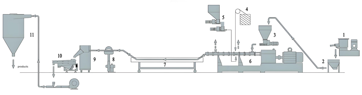
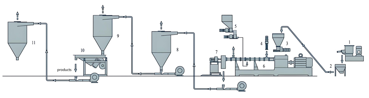
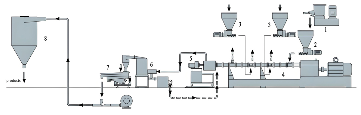
The production of wear-resistant masterbatch using twin screw extrusion involves several critical stages, each requiring careful control and monitoring to ensure consistent product quality. The process combines raw material preparation, extrusion processing, and post-extrusion handling into a continuous manufacturing operation.
Raw Material Preparation
The quality of the finished masterbatch depends heavily on the preparation of raw materials before extrusion. All additives must be properly dried to remove moisture that could cause hydrolysis reactions or steam generation during extrusion. Synthetic silica and ceramic fillers typically require drying at 120 to 150 degrees Celsius for 4 to 6 hours to achieve moisture contents below 0.1 percent. Carrier resins also require drying, generally at 80 to 100 degrees Celsius for 3 to 4 hours, to prevent moisture-related defects in the extruded product.
Particle size reduction and classification of raw additives may be necessary for certain formulations. Agglomerated particles must be broken down to achieve the target particle size distribution, as oversized agglomerates create processing problems and result in poor dispersion in the final product. High-shear mixing of additives with carrier resin before extrusion can improve wetting and dispersion characteristics.
The pre-blending stage involves combining all formulation components in the correct proportions. This mixing must be thorough enough to ensure uniform distribution of all additives throughout the carrier resin before entering the extruder. Ribbon blenders or high-intensity mixers are typically used for this purpose, with mixing times of 10 to 20 minutes providing adequate homogeneity for most formulations.
Twin Screw Extrusion Processing
The extrusion stage transforms the pre-blended formulation into a homogeneous masterbatch through the combined effects of heat, pressure, and mechanical mixing. The co-rotating twin screw extruder provides the distributive and dispersive mixing required to break down agglomerates and achieve uniform additive distribution.
Material enters the extruder through a loss-in-weight feeder that maintains consistent throughput based on the target production rate. The feeding zone features deep screw flights that accept the loosely packed pre-blend and begin the compression and conveyance of the material. As the material moves through the extrusion zones, the screw configuration transitions to progressively shallower flights that compress and work the material.
The melting zone subjects the formulation to intense shear as the carrier resin transitions from solid to molten state. This zone typically features kneading block elements that create high stress on the material, breaking down any remaining agglomerates and incorporating additives into the polymer matrix. The combination of thermal energy from the barrel heating zones and mechanical energy from screw rotation provides the energy input required for melting and mixing.
The mixing zones maintain the material in a thoroughly mixed molten state while continuing to distribute additives throughout the polymer. The residence time distribution in these zones determines the extent of mixing achieved, with longer average residence times and narrower distributions generally providing more consistent product quality. The screw configuration in these zones typically includes forward conveying elements mixed with neutral or reverse kneading blocks that increase fill level and mixing intensity.
The devolatilization zone removes any volatile contaminants or residual moisture from the formulation through vacuum extraction ports along the barrel. This stage is particularly important for moisture-sensitive formulations and helps prevent voids or bubbles in the finished masterbatch granules.
The melt exits the extruder through a specialized die plate that creates multiple strands of material. These strands enter a water cooling bath that solidifies the masterbatch before it enters the pelletizer. The cooling water temperature and strand tension must be carefully controlled to prevent deformation or sticking of the granules.
Pelletizing and Finishing
The underwater pelletizer cuts the solidified strands into uniform granules of the target size, typically between 2 and 4 millimeters in length. The cutting speed and water flow rate must be synchronized to produce granules with consistent dimensions and minimal fines or oversized particles.
After pelletizing, the granules enter a centrifugal drier that removes surface moisture before packaging. The dried masterbatch is then transferred to packaging equipment where it is filled into bags or containers with appropriate moisture barriers. The packaged product should be stored in a dry environment to prevent moisture absorption before use.
Production Equipment Introduction
Successful production of wear-resistant masterbatch requires selection of appropriate extrusion equipment capable of handling the high filler loadings and processing requirements of these formulations. Twin screw extruders from Kerke in the KTE series provide a range of capabilities suited to different production scales and formulations.
Kerke KTE-36B Twin Screw Extruder
The Kerke KTE-36B represents an entry-level production platform suitable for pilot scale operations and small batch production. This compact twin screw extruder features a screw diameter of 35.6 millimeters and a length-to-diameter ratio of 40:1, providing adequate residence time for most wear-resistant formulations. The KTE-36B achieves throughput rates of 20 to 100 kilograms per hour, making it suitable for product development, small-scale commercial production, or specialty formulations requiring close process control.
The modular barrel configuration allows processors to customize heating and cooling zones to match specific formulation requirements. The KTE-36B includes six independent temperature control zones plus the die zone, enabling precise temperature profiling throughout the extrusion process. The screw elements are fully modular, allowing custom configurations for different formulations and processing requirements.
Kerke KTE-50B Twin Screw Extruder
The mid-range KTE-50B offers increased production capacity while maintaining excellent process flexibility. With a screw diameter of 50.5 millimeters and a standard length-to-diameter ratio of 40:1, this extruder delivers throughput rates between 80 and 200 kilograms per hour. The larger screw diameter provides higher throughput capability while maintaining adequate shear rates for effective mixing.
The KTE-50B features eight barrel heating zones plus the die zone, supporting more sophisticated temperature control strategies. The increased barrel volume allows processing of higher viscosity formulations that might challenge smaller equipment. This model represents an excellent choice for manufacturers transitioning from pilot scale to commercial production.
Kerke KTE-65B Twin Screw Extruder
The KTE-65B targets medium-scale commercial production with throughput rates of 200 to 450 kilograms per hour. The 62.4 millimeter screw diameter provides substantial throughput capability while maintaining good mixing performance. This model includes ten barrel temperature zones plus the die zone, enabling fine control of the extrusion process for demanding formulations.
The KTE-65B features reinforced screw elements and barrel components designed for continuous production operation. The increased torque capacity allows processing of high-loading formulations that would exceed the capability of smaller equipment. This model serves as a standard platform for many commercial wear-resistant masterbatch production operations.
Kerke KTE-75B Twin Screw Extruder
High-volume production requirements are addressed by the KTE-75B, which achieves throughput rates between 300 and 800 kilograms per hour. The 71 millimeter screw diameter and extended length-to-diameter ratio of 48:1 provide both high capacity and extended residence time for thorough mixing of demanding formulations. The KTE-75B features twelve barrel heating zones plus die zone temperature control.
The KTE-75B incorporates advanced mixing elements optimized for high-filler loading formulations. The screw configuration includes specialized distributive mixing elements that improve additive distribution without excessive shear heating. This model is suitable for manufacturers with established markets seeking capacity expansion or improved production efficiency.
Kerke KTE-95D Twin Screw Extruder
Maximum production capacity is available through the KTE-95D, designed for large-scale commercial and industrial masterbatch production. This high-capacity twin screw extruder features a 93 millimeter screw diameter and achieves throughput rates between 1000 and 2000 kilograms per hour. The extended barrel length provides sufficient residence time for thorough mixing even at the highest throughput rates.
The KTE-95D incorporates advanced drive and control systems designed for continuous production operation. The modular barrel configuration supports custom configurations including multiple devolatilization zones, side-feeder ports, and specialized mixing elements. This model serves major production facilities requiring high-volume output of consistent-quality masterbatch.
Parameter Settings for Wear-Resistant Masterbatch Production
Optimal parameter settings for wear-resistant masterbatch production depend on the specific formulation, equipment configuration, and target product characteristics. Processors must develop parameter sets that balance mixing quality, throughput, energy consumption, and product quality.
Temperature Profile Settings
The barrel temperature profile significantly affects melting behavior, mixing efficiency, and product quality. For standard wear-resistant formulations based on polyethylene carriers, typical temperature profiles range from 160 to 220 degrees Celsius across the barrel zones. The feeding zone operates at the lower end of this range to prevent premature melting and agglomeration of additives, while the compression and mixing zones use progressively higher temperatures to ensure complete melting and good mixing.
Formulations based on polypropylene carriers require higher processing temperatures, typically ranging from 200 to 260 degrees Celsius. The higher melting point of polypropylene requires elevated temperatures to achieve the melt viscosity necessary for effective mixing. However, excessive temperatures can cause thermal degradation of additives or carrier resin, so processors must balance temperature against processing time and shear heating effects.
The die zone temperature must be set high enough to maintain the melt in a fluid state for strand formation but low enough to prevent thermal degradation. Typical die temperatures range from 180 to 240 degrees Celsius depending on the carrier resin and throughput rate. The die pressure should be monitored to ensure consistent melt flow through all die openings.
Screw Speed and Throughput
Screw speed affects both mixing intensity and throughput rate, with higher speeds providing increased shear for dispersion but also greater energy input and potential for overheating. For most wear-resistant formulations, screw speeds between 200 and 400 revolutions per minute provide good balance between mixing quality and processing stability.
Throughput rate is typically controlled by the feeder speed, which determines the fill level within the extruder and thus the residence time and mixing efficiency. Higher throughput rates reduce residence time and may compromise mixing quality, while lower rates increase residence time but reduce production efficiency. The optimal throughput depends on the specific formulation and equipment size.
For the KTE-36B, throughput rates of 30 to 60 kilograms per hour typically provide good results for most wear-resistant formulations. The KTE-50B operates efficiently at 100 to 150 kilograms per hour, while the KTE-65B achieves quality results at 250 to 350 kilograms per hour. The larger KTE-75B and KTE-95D units operate at 400 to 600 and 1200 to 1600 kilograms per hour respectively for these formulations.
Back Pressure and Melt Pressure
Melt pressure within the extruder affects fill level, residence time, and mixing efficiency. Higher back pressure at the die increases fill level in the mixing zones, providing more intensive mixing but also greater energy consumption. Pressure is controlled by the die configuration, including the number and size of die openings and any restriction elements in the screw configuration.
Typical melt pressures for wear-resistant masterbatch production range from 5 to 15 megapascals depending on the formulation and equipment. Monitoring melt pressure provides important information about process stability and can indicate problems such as feed rate variations, temperature fluctuations, or equipment malfunctions.
Vacuum and Devolatilization Settings
Devolatilization zones operated under vacuum help remove moisture, residual monomers, and other volatiles from the formulation. Vacuum levels between 0.5 and 0.9 bar provide effective volatiles removal without causing excessive foam formation. The vacuum zone location and number of zones depend on the specific formulation and volatility characteristics.
For moisture-sensitive formulations, proper devolatilization is essential to achieve the low moisture content required in the finished product. Inadequate devolatilization can cause steam formation in the melt, resulting in voids or bubbles in the extruded strands and poor product quality.
Equipment Price
The investment required for twin screw extrusion equipment varies significantly based on production capacity, features, and configuration. Kerke offers the KTE series across a range of price points to serve different market segments and production requirements.
The Kerke KTE-36B, suitable for pilot scale and small batch production, is priced between 25,000 and 35,000 dollars. This entry-level platform provides excellent value for product development and low-volume specialty production. The compact design minimizes installation requirements while delivering professional-grade mixing performance.
The Kerke KTE-50B, targeting small to medium-scale commercial production, ranges from 40,000 to 60,000 dollars. The increased capacity and enhanced features make this model attractive for growing businesses establishing commercial production capabilities. The additional barrel zones and improved control systems justify the higher investment for production-scale operations.
Medium-scale production capacity is available through the Kerke KTE-65B at prices between 50,000 and 80,000 dollars. This model provides the capacity and features required for established commercial production while maintaining competitive pricing. The robust construction and reliability features support continuous production operation.
High-volume production is served by the Kerke KTE-75B in the price range of 70,000 to 100,000 dollars. The increased throughput capability and extended features make this model suitable for manufacturers with significant production requirements. The investment is justified by reduced per-unit production costs and improved production efficiency.
Maximum capacity production is available through the Kerke KTE-95D at prices between 120,000 and 200,000 dollars. This industrial-scale extruder delivers throughput rates up to 2000 kilograms per hour with full-featured control and automation systems. The higher investment reflects the advanced engineering and capacity required for large-scale production facilities.
Problems in Production Process and Solutions
Production of wear-resistant masterbatch presents several technical challenges that require careful attention to process conditions and equipment configuration. Understanding common problems and their solutions helps processors maintain consistent quality and efficient operation.
Problem: Inconsistent Dispersion Quality
Inconsistent dispersion of wear-resistant additives results in products with variable performance characteristics. This problem manifests as streaks or uneven color in compounded products, inconsistent surface hardness, and poor batch-to-batch reproducibility.
Root Cause Analysis
Inadequate dispersion typically results from insufficient shear stress during mixing, improper screw configuration, or inadequate pre-blending of raw materials. When particles are not sufficiently wetted by the polymer matrix, they form agglomerates that resist breakdown during extrusion. Equipment issues such as worn screw elements, damaged barrel liners, or incorrect temperature profiles can also contribute to dispersion problems.
The quality of raw materials plays an important role in dispersion performance. High moisture content in fillers causes particle agglomeration and reduced dispersibility. Inadequate surface treatment of additives prevents proper bonding with the polymer matrix. Inconsistent particle size distribution in raw materials creates processing difficulties as oversized particles resist dispersion.
Solutions
Increasing shear intensity through screw configuration modifications often resolves dispersion problems. Adding additional kneading block elements in the mixing zones increases stress on the material and improves agglomerate breakdown. Adjusting the staggering angle of kneading elements from the standard 45 degrees to the more aggressive 60 or 90 degree configuration increases shear intensity.
Temperature profile adjustments can improve dispersion by reducing melt viscosity and increasing the effectiveness of mechanical mixing. Lowering temperatures in the mixing zones increases viscosity and shear stress, while ensuring complete melting prevents unmelted particles from causing defects. However, temperatures must remain high enough to prevent excessive torque and motor overload.
Implementing high-shear pre-blending before extrusion improves the wetting of additives by the polymer carrier. Using a high-intensity mixer or internal mixer for pre-blending breaks down large agglomerates and ensures thorough incorporation of all components before the material enters the extruder.
Prevention Methods
Establishing regular quality control testing of finished masterbatch helps identify dispersion problems before they affect customer products. Simple tests such as microscopy examination of diluted samples, melt flow measurement, or tensile testing of compounded specimens provide valuable quality indicators. Setting specification limits and acceptance criteria ensures consistent product quality.
Preventive maintenance of extrusion equipment maintains mixing performance over time. Regular inspection of screw elements for wear, checking barrel liner condition, and verifying temperature controller accuracy prevents performance degradation. Recording operating parameters for each production batch enables identification of trends that might indicate developing problems.
Problem: High Extruder Torque and Motor Overload
Excessive torque requirements during processing strain the extruder drive system and can trigger automatic shutdowns or cause equipment damage. This problem limits throughput and creates unstable operating conditions.
Root Cause Analysis
High torque requirements result from excessive viscosity in the material being processed, which can be caused by low temperatures, high filler loadings, or formulation issues. When the extruder is pushed beyond its design capacity, the increased material resistance exceeds the drive system capability. Screw configuration with excessive restriction elements creates back pressure that increases torque demand beyond sustainable levels.
Feed rate exceeding the capability of the equipment creates overfilling conditions that dramatically increase torque requirements. Uneven feeding or fluctuations in feed rate create periodic torque spikes that stress the drive system. The presence of unmelted material or foreign objects in the feed can also cause sudden torque increases.
Solutions
Reducing throughput rate immediately alleviates torque problems by decreasing the fill level and material processing load. Adjusting the feed rate to match the equipment capability restores stable operation while identifying the maximum sustainable throughput for the specific formulation.
Optimizing the temperature profile increases melt flow and reduces viscosity, directly addressing torque issues caused by inadequate melting. Raising temperatures in the compression and metering zones improves melting efficiency and reduces power requirements. However, temperatures must remain below degradation levels for the specific formulation.
Modifying the screw configuration to reduce restriction elements decreases back pressure and torque demand. Replacing some kneading blocks with conveying elements, or adjusting staggering angles to reduce mixing intensity, can significantly reduce torque requirements while maintaining acceptable product quality.
Prevention Methods
Proper formulation development ensures that masterbatch formulations are compatible with available equipment capabilities. Testing formulations at various throughput rates during development identifies optimal operating conditions and potential problems before production scale-up. Building safety margins into formulation viscosity and processing requirements provides buffer for normal variations.
Regular monitoring of torque levels during production enables early detection of developing problems. Establishing normal operating ranges and alarm thresholds provides warning of conditions that might lead to overload situations. Maintaining detailed production records supports troubleshooting when unusual torque readings occur.
Problem: Die Plate Blockage and Uneven Flow
Blockage of die openings and non-uniform flow through the die plate create quality problems in the finished masterbatch and can cause equipment damage from pressure buildup.
Root Cause Analysis
Die blockage results from solidification of high-melting-point components, accumulation of degraded material, or contamination in the melt. When the die temperature is too low, viscous regions form in the die openings that restrict flow and eventually block entirely. Thermal degradation of the polymer or additives creates high-viscosity products that resist flow and accumulate in the die.
Non-uniform flow patterns indicate problems with melt distribution in the extruder or pressure imbalances at the die entry. The die design must provide equal flow resistance for all openings to achieve uniform throughput. Worn die components or accumulated material create flow restrictions that disrupt uniform distribution.
Solutions
Increasing die zone temperature resolves most blockage problems caused by inadequate melt fluidity. The die temperature should be set at least 10 to 20 degrees Celsius above the temperature in the final barrel zone to ensure complete melting and good flow through the die openings. Monitoring die pressure helps identify developing blockage before complete obstruction occurs.
Cleaning the die plate and die openings removes accumulated material that restricts flow. Regular cleaning schedules prevent buildup that leads to blockage during production runs. Using appropriate cleaning compounds and procedures ensures thorough removal of all deposits without damaging die components.
Redesigning the die plate for better flow distribution addresses persistent non-uniform flow problems. The die land length, inlet geometry, and flow channel dimensions all affect flow uniformity. Computational fluid dynamics analysis can help optimize die designs for specific formulations and throughput requirements.
Prevention Methods
Implementing regular die maintenance prevents accumulation that leads to blockage. Establishing cleaning intervals based on formulation characteristics and production experience ensures consistent operation. Documenting cleaning procedures and results supports continuous improvement of maintenance practices.
Controlling raw material quality prevents contamination that can cause die blockage. Establishing specifications for raw material purity and implementing incoming inspection procedures identify potential problems before they affect production. Using proper storage and handling procedures prevents contamination during storage and handling.
Maintenance of Twin Screw Extruders for Masterbatch Production
Regular maintenance of twin screw extrusion equipment ensures consistent product quality, extends equipment life, and prevents unexpected downtime. A comprehensive maintenance program addresses both scheduled maintenance activities and condition monitoring to identify developing problems.
Screw Element and Barrel Maintenance
The screw elements and barrel liners represent the highest-wear components in twin screw extrusion equipment. Wear occurs from the combined effects of abrasive fillers, high temperatures, and continuous mechanical stress during processing. Inspecting screw elements regularly identifies wear patterns and determines when replacement is necessary.
Screw element wear reduces mixing efficiency and allows material leakage between element segments, degrading product quality. Measuring flight diameters and comparing with new component specifications quantifies wear levels. Replacing worn elements before they fail completely prevents more serious problems and maintains consistent processing performance.
Barrel liner wear creates similar problems by allowing material to leak around screw elements and reducing effective compression ratios. Borescope inspection of barrel interiors identifies wear locations and severity. Replacing barrel liners restores the original clearances and processing performance of the equipment.
Temperature Control System Maintenance
Accurate temperature control is essential for consistent masterbatch production. The temperature control system includes barrel heating zones, cooling systems, temperature sensors, and controllers. Regular calibration of temperature sensors ensures accurate temperature measurement and control.
Checking heating element continuity and resistance identifies elements approaching failure. Burned-out elements create temperature control problems that affect product quality. Replacing suspect heating elements during scheduled maintenance prevents failures during production.
Cooling system maintenance ensures proper operation of water-cooled zones and oil cooling systems. Flow rates and temperatures should be verified regularly. Cleaning cooling passages removes scale and deposits that reduce cooling efficiency. Poor cooling performance causes temperature control difficulties that affect product quality.
Drive System Maintenance
The drive system including motor, gearbox, and coupling requires regular attention to ensure reliable operation. Gearbox oil quality and level should be checked according to manufacturer recommendations. Oil analysis provides early warning of developing problems such as wear or contamination.
Motor condition monitoring including vibration analysis and insulation testing identifies problems before motor failure occurs. Maintaining motor cooling systems ensures adequate heat removal during operation. Checking electrical connections and terminals prevents intermittent operation and potential safety hazards.
Coupling inspection verifies alignment and condition of drive system components. Worn couplings create vibration and misalignment that accelerate wear throughout the drive system. Replacing couplings on scheduled intervals prevents unexpected failures and equipment damage.
Feeding System Maintenance
Accurate and consistent feeding is essential for stable extrusion operation. The feeder system includes loss-in-weight hoppers, screw feeders, and control systems. Calibration verification ensures accurate feed rate control during production.
Feeder screw inspection identifies wear that affects feeding accuracy. Worn feeder screws deliver inconsistent quantities that cause process instability and product variation. Replacing worn feeder components restores accurate feeding performance.
Hopper and feed throat maintenance prevents material bridging, contamination, and feeding problems. Regular cleaning removes material buildup that can cause flow problems. Inspecting hopper liners and feed throat components identifies wear or damage that might affect feeding performance.
Pelletizing System Maintenance
The pelletizing system including die plate, knife blade, and drive components requires regular attention to maintain granule quality. Knife blade sharpness directly affects cut quality and granule appearance. Replacing dull blades prevents irregular granule shapes and excessive fines production.
Die plate inspection verifies condition of die holes and land surfaces. Worn or damaged die holes create off-specification granules. Regular cleaning removes polymer buildup that can restrict flow and affect cut quality. Die plate replacement may be necessary when wear or damage exceeds acceptable limits.
Pelletizer drive system maintenance including belt tension, gear alignment, and motor condition ensures consistent cutting performance. Regular lubrication of rotating components prevents premature wear and failure. Checking water distribution systems verifies adequate cooling of freshly cut granules.
FAQ
What is the recommended filler loading level for general-purpose wear-resistant masterbatch?
General-purpose wear-resistant masterbatch typically contains 30 to 50 percent active filler content, with 35 to 40 percent being the most common loading for applications requiring balanced performance and processibility. Higher loadings up to 50 to 60 percent are possible but require specialized processing equipment and may present challenges in dispersion quality and extrusion stability.
Can wear-resistant masterbatch be used with recycled polymer materials?
Wear-resistant masterbatch can be incorporated into recycled polymer compounds, though the final performance depends on the quality and characteristics of the recycled material. Recycled polymers may have already undergone some thermal degradation that affects their ability to accept high filler loadings. Testing specific combinations is recommended to verify compatibility and performance.
What particle size is optimal for synthetic silica wear-resistant additives?
Median particle sizes between 2 and 5 micrometers provide the best balance of wear resistance and dispersion quality. Particles smaller than 1 micrometer offer improved scratch resistance but present greater dispersion challenges and may increase melt viscosity significantly. Particles larger than 10 micrometers are easier to disperse but provide less effective surface protection due to larger particle sizes at the surface.
How does wear-resistant masterbatch affect the colorability of plastic products?
Wear-resistant masterbatch typically contains high loadings of mineral or ceramic fillers that may affect the colorability of finished products. Light-colored or translucent products may appear slightly cloudy when high loading masterbatches are used. For applications requiring specific colors, testing with representative formulations is recommended to verify color matching results.
What storage conditions are recommended for wear-resistant masterbatch?
Wear-resistant masterbatch should be stored in a dry environment with relative humidity below 60 percent to prevent moisture absorption. Storage temperatures between 15 and 30 degrees Celsius are recommended. Proper storage in sealed packaging protects the product from moisture and contamination until use. Typical shelf life under proper storage conditions is 12 to 24 months depending on the specific formulation and packaging.
How does PTFE content affect the properties of wear-resistant masterbatch?
PTFE addition provides excellent lubricity and release properties along with improved scratch resistance. However, PTFE can create processing challenges due to its tendency to agglomerate and its high melt viscosity. PTFE-containing masterbatches typically include PTFE loadings between 15 and 25 percent, with higher concentrations reserved for specialized applications requiring exceptional lubricity.
What is the difference between anti-scratch and wear-resistant masterbatch?
While the terms are sometimes used interchangeably, anti-scratch masterbatch typically refers to additives that prevent surface scratching from light contact, while wear-resistant masterbatch addresses more severe abrasion and surface damage from repeated contact and friction. Many formulations combine both properties, providing protection against both light scratching and more significant wear damage.
Can wear-resistant masterbatch be blended with other additive masterbatches?
Wear-resistant masterbatch can be blended with other masterbatch types such as colorants or other functional additives, though compatibility testing is recommended. Potential interactions between different additive systems should be evaluated, particularly for high-loading formulations. Blending at the extrusion stage rather than pre-blending the masterbatches often provides better dispersion of all additives.
Conclusion
The production of wear-resistant and anti-scratch masterbatch using twin screw extrusion technology offers manufacturers a reliable path to high-quality functional compounds for demanding applications. The controlled mixing environment, precise temperature management, and scalable equipment options provided by twin screw extruders enable consistent production of these specialized formulations across a wide range of production scales.
Successful production requires attention to formulation development, process optimization, and quality control throughout the manufacturing operation. Understanding the relationships between formulation characteristics, processing parameters, and finished product properties enables processors to develop robust manufacturing processes that deliver consistent quality. The equipment investment required for wear-resistant masterbatch production is justified by the performance benefits and market value of these specialized compounds.
As the demand for durable plastic products continues to grow across automotive, electronics, and consumer goods applications, wear-resistant masterbatch will remain an important product category. Processors investing in twin screw extrusion capabilities for these formulations position themselves to serve expanding markets while building expertise in functional masterbatch production. The combination of sound process engineering, quality-focused operations, and appropriate equipment selection creates the foundation for successful wear-resistant masterbatch manufacturing.