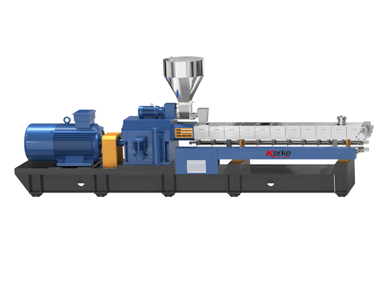
As the core power component of the twin-screw extruder, the operating status of the main motor directly determines the stability of the equipment. Abnormal noise is mostly an early warning signal caused by mechanical friction, electrical faults, or abnormalities in associated systems. It is necessary to accurately troubleshoot by combining noise characteristics and accompanying phenomena (such as current fluctuation and abnormal temperature rise) to avoid serious problems such as motor burnout and screw jamming due to fault expansion. The following is a detailed analysis of the causes and corresponding solutions:
I. Mechanical Transmission System Failures (Most Common Cause)
(I) Damage to Main Motor Bearings or Lubrication Failure
Causes: Long-term high-speed operation of bearings leads to ball wear and cage deformation; lack, aging, or contamination of grease causing dry friction; excessive fit clearance between the motor shaft and bearings resulting in radial/axial movement during operation. The noise is usually a continuous “buzzing” or “creaking” friction sound, or a periodic “clacking” sound, accompanied by abnormal temperature rise at the bearing end (exceeding 70℃).
Solutions:
- Stop the machine and cut off the power, remove the motor end cover and protective shield, rotate the motor shaft by hand to feel for jamming, looseness, or uneven resistance, and check if the bearing seal is damaged and if the grease is discolored or caked.
- If lubrication is insufficient, thoroughly clean the old grease inside the bearing, and add a suitable type of high-temperature grease (such as lithium-based grease) in an amount of 1/3 to 1/2 of the internal space of the bearing to avoid heat accumulation due to excessive grease.
- If the bearing is worn, has peeling balls, or a damaged cage, directly replace it with a high-precision bearing of the same model. After replacement, correct the coaxiality of the shaft to ensure smooth operation.
(II) Bending or Eccentricity of Motor Rotor Shaft
Causes: Shaft deformation due to motor overload; impact force during transportation or installation; thermal deformation of the shaft due to long-term high-temperature operation. The noise manifests as a “whirring” sound that intensifies with increasing speed, accompanied by obvious motor vibration, and shaft end swing can be observed in severe cases.
Solutions:
- Use a dial indicator to measure the radial runout of the motor shaft. If it exceeds 0.05mm, the shaft is bent and needs to be sent for repair and correction, or the rotor shaft should be directly replaced.
- After replacement/correction, reinstall the motor to ensure that the coaxiality between the shaft and the coupling meets the requirements (radial runout ≤ 0.02mm, axial runout ≤ 0.01mm).
(III) Carbon Brush Wear or Poor Contact (Applicable to Wound Rotor Motors)
Causes: Carbon brushes worn to the limit thickness (usually ≤ 5mm), surface oxidation or carbon deposition; loose brush holders, excessive contact gap between carbon brushes and commutators, resulting in electric sparks accompanied by “sizzling” noise during operation, and ablation marks on the commutator surface in severe cases.
Solutions:
- Remove the motor carbon brush cover, check the wear of carbon brushes, replace excessively worn carbon brushes, and ensure that the new carbon brushes are closely attached to the commutator (contact area ≥ 80%).
- Polish the oxide layer and carbon deposits on the commutator surface with fine sandpaper, clean the dust inside the brush holder, adjust the position of the brush holder, and ensure uniform contact pressure between carbon brushes and the commutator (usually 0.2-0.3MPa).
II. Electrical Control System Failures
(I) Thyristor Rectifier Circuit Failure
Causes: Damage or breakdown of one of the thyristor components in the main motor thyristor rectifier circuit, leading to abnormal rectifier output waveform and unbalanced motor power supply, resulting in “buzzing” electromagnetic noise, accompanied by motor current fluctuation and unstable speed.
Solutions:
- After stopping the machine and cutting off the power, use a multimeter to test the on-off performance of each thyristor component, identify and replace damaged components with thyristors of the same model, and check if the wiring of the trigger circuit is loose or oxidized.
- After replacement, perform no-load power-on testing, observe whether the motor speed and current are stable, and ensure that the output waveform of the rectifier circuit is normal.
(II) Inverter Failure or Improper Parameter Setting
Causes: Damage to IGBT modules or aging of capacitors inside the inverter, leading to output frequency fluctuation; unreasonable parameter settings (such as too short acceleration time, too low carrier frequency) causing motor electromagnetic resonance, resulting in low-frequency “rumbling” noise, accompanied by increased motor vibration.
Solutions:
- Check if there is a fault code on the inverter display panel, troubleshoot internal components (such as modules and capacitors) according to the code, and contact professional personnel for maintenance or replacement of the inverter if necessary.
- Optimize inverter parameters: appropriately extend the acceleration time (matching the motor load characteristics), adjust the carrier frequency to 2-5kHz (to reduce electromagnetic noise), and confirm that the power and voltage levels of the inverter and motor match.
(III) Abnormal Power Supply Line
Causes: Unbalanced three-phase voltage (deviation exceeding 5%), poor line contact, blown fuses, or loose terminal blocks, leading to uneven stress on the motor stator windings, resulting in electromagnetic noise, and possibly accompanied by motor heating and speed reduction.
Solutions:
- Use a multimeter to test the three-phase input voltage, check for loose or oxidized parts of the line, tighten terminal blocks, replace blown fuses, and ensure balanced three-phase voltage.
- Check the insulation performance of the motor stator windings. If the insulation resistance is lower than 0.5MΩ, dry the windings to eliminate short-circuit hazards.
III. Associated System Failures (Easily Misjudged as Motor Faults)
(I) Motor Overload Noise Caused by Screw System Failures
Causes: Metal foreign objects or hard impurities mixed in materials jamming the screws or increasing friction between screws and the barrel; screw deformation, phase misalignment, or improper installation of adjustment gaskets leading to screw meshing interference; heater failure or poor material plasticization increasing extrusion resistance, causing the motor to operate under overload with a “muffling” noise, accompanied by a sharp rise in current.
Solutions:
- Stop the machine immediately, turn off the heater, wait for the barrel temperature to drop to room temperature, disassemble the machine head and screws, clean internal foreign objects and wall-sticking materials, check the wear of screws and the barrel, and repair or replace them if necessary.
- Correct the screw phase and coaxiality, adjust the thickness of adjustment gaskets to ensure normal screw meshing without interference; check the working status of each section of the heater, replace faulty heaters, reset the process temperature, and ensure uniform material plasticization.
(II) Coupling Failure
Causes: Aging or damage of the coupling elastomer between the motor and reducer, loose coupling bolts, or excessive coaxiality deviation, resulting in “impact noise” during operation. The noise intensifies with load changes and is easily misjudged as motor bearing noise.
Solutions:
- Disassemble the coupling, replace the aging elastomer, tighten the connecting bolts, and correct the coupling coaxiality with a dial indicator (both radial and axial runout must meet equipment requirements).
- Check the surface wear of the coupling. If there are severe scratches or deformation, directly replace the coupling to avoid motor shaft damage due to uneven power transmission.
(III) Lubrication System Failure
Causes: Lubricating oil pump failure, clogged oil suction pipe, or low lubricating oil pressure, leading to insufficient lubrication of motor bearings and reducers, resulting in dry friction noise, accompanied by abnormal bearing temperature rise.
Solutions:
- Check the oil level and oil quality in the lubricating oil tank, supplement or replace the lubricating oil of the appropriate model, clean the clogged oil suction pipe, overhaul the lubricating oil pump, and adjust the system pressure to the specified range.
- Regularly maintain the lubrication system, replace filters, clean oil circuits, and avoid impurity mixing affecting lubrication effect.
IV. Precautions for Troubleshooting and Prevention
- Troubleshooting sequence: First run the motor under no-load to determine if the noise comes from the motor itself; then perform load testing to troubleshoot associated system failures, following the principle of “from simple to complex, from surface to inside”.
- Safe operation: All maintenance must be carried out after stopping the machine and cutting off the power. Wait for the inverter induced electricity to dissipate (usually more than 5 minutes) to avoid electric shock; make positioning marks when disassembling screws and motors to ensure reinstallation accuracy.
- Regular maintenance: Inspect the lubrication status of motor bearings and carbon brush wear monthly; test the performance of electrical lines, thyristors, and inverters quarterly; regularly clean the material screening device to prevent foreign objects from entering the screw system.
- Record and traceability: Record the occurrence time, working conditions, troubleshooting process, and solutions of abnormal noise faults to provide reference for similar faults in the future.