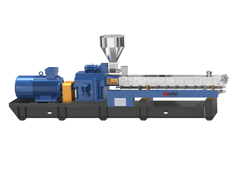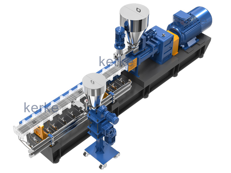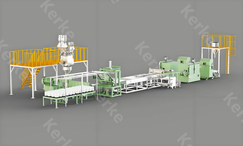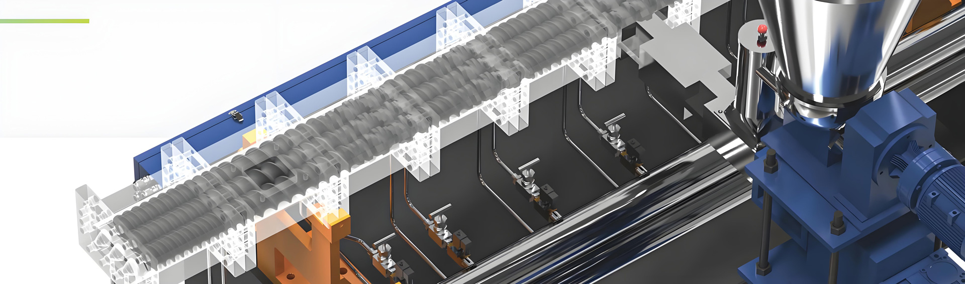
As core equipment in fields such as rubber and plastic processing and composite material preparation, twin-screw extruders often experience faults due to abnormalities in key modules including the electrical drive system, feeding system, heating and plasticizing system, lubrication and transmission system, and auxiliary devices. Combined with equipment structure and operation mechanism, the core causes of various common faults are analyzed in detail below.
I. Fault Causes of the Electrical Drive System
1. Main Motor Failed to Start
- Abnormal Operation Procedure: The startup sequence does not comply with equipment regulations, such as starting the main motor before activating the lubricating oil pump and cooling system, or without completing the preheating process, triggering the equipment interlock protection mechanism; some equipment requires resetting historical fault codes first, and failure to do so will prevent startup.
- Circuit and Component Faults: Burnout of fuses and air switches in the main motor circuit, oxidation, adhesion, or failure to close of contactor contacts; incorrect inverter parameter settings, unrelieved induced electricity of the inverter, or damage to one or more thyristors in the thyristor rectifier circuit and faults in the trigger circuit, leading to interruption of the power supply circuit or abnormal drive signals; aging of cables and damage to insulation layers causing short circuits can also block power supply.
- Triggered Protection Devices: Emergency stop button not reset, open circuit of the emergency stop loop, unrelieved interlock devices linked with the main motor (such as oil temperature, oil pressure, and vacuum degree protection); PLC program errors, communication module faults in the control system, or interruption of signal transmission between the Human-Machine Interface (HMI) and the controller, blocking the issuance of startup commands; failure to manually reset the motor overload protector and thermal relay after actuation will also restrict startup.
2. Abnormal Operation of the Main Motor (Abnormal Noise, Excessive Temperature Rise, Unstable Current)
- Causes of Abnormal Noise: Severe wear of motor bearings, peeling of balls, or dry lubricating grease, resulting in frictional and impact noise from rotating components; three-phase current imbalance of the motor caused by thyristor rectifier circuit faults, generating electromagnetic noise during operation; broken rotor bars and short circuits in the stator windings of the motor can also be accompanied by abnormal electromagnetic noise, along with increased vibration.
- Excessive Temperature Rise of Bearings: Insufficient, deteriorated, or mismatched lubricating grease for bearings, failing to form an effective oil film; long-term overload operation of bearings and improper installation clearance (too tight or too loose), leading to increased wear and frictional heat generation; damage to cooling fans and blockage of heat dissipation air ducts, reducing the heat dissipation efficiency of bearings and causing continuous temperature rise.
- Unstable Current: Fluctuations in feeding quantity and excessive moisture content of materials (rapid evaporation of moisture during heating) resulting in uneven load; failure of a certain section of the heater and large temperature control deviation, causing fluctuations in material plasticization degree and increasing load fluctuations of the motor; misalignment of screw adjustment pads and phase deviation leading to component interference, generating periodic load impacts; unstable output frequency of the inverter and broken rotor bars of the motor can also cause current to fluctuate.
II. Fault Causes of the Feeding System
1. Die Pressure Fluctuation
- Insufficient control precision of the main motor speed and lagging speed regulation response of the inverter, resulting in unstable screw conveying speed; fluctuations in the speed of the feeding motor and excessive wear clearance of the reduction gearbox, causing uneven material supply, breaking the material balance of the extrusion system, and triggering periodic changes in die pressure; excessive clearance between the feeding screw and the barrel, and changes in material leakage volume can also aggravate pressure fluctuations.
- Material jamming inside the feeder and material bridging in the hopper (especially prone to occur with powdery and viscous materials), leading to interrupted or uneven feeding; faults of the hopper level gauge, failing to timely feed back material quantity changes and unable to supplement materials or adjust feeding speed in a timely manner; excessive differences in material particle size and uneven mixing can also affect feeding stability, thereby fluctuating die pressure.

2. Sudden Drop in Extrusion Output
- Mechanical faults of the feeding system, such as wear and deformation of the feeding screw, wear and jamming of transmission gears and chains, or loose couplings; insufficient material in the hopper without timely supplementation, and failure of the level alarm to trigger a reminder; faults of the stirring device in the feeder hopper (such as jamming of the stirring paddle and motor damage), leading to material caking and inability to fall, ultimately causing interruption or sharp reduction of material supply.
- Entry of metal debris and hard foreign objects (such as bolts and impurity particles) into the extrusion system, jamming the screw and hindering material conveying, resulting in a sudden drop in extrusion output or even zero output; wear and fracture of screw elements, or severe wear of the barrel inner wall, leading to a significant decrease in material conveying efficiency; severe blockage of the die filter without timely replacement, and excessive back pressure inhibiting material extrusion, which can also cause a drop in extrusion output.
III. Fault Causes of the Heating and Plasticizing System
1. Unsmooth Die Discharging or Blockage
- Heater faults: Burnout, poor contact, and oxidation loosening of terminal blocks of a certain section of the heating coil, or failure of the Solid State Relay (SSR) and damage to the thyristor, leading to insufficient temperature in the corresponding area, incomplete plasticization of materials, and accumulation and blockage of semi-molten materials at the die; scaling and material accumulation on the surface of the heating coil, poor heat dissipation leading to reduced heating efficiency, which can also indirectly affect plasticization effect.
- Improper process parameters: Low set operating temperature, excessive heating rate (large internal and external temperature difference of materials, insufficient melting), or wide molecular weight distribution and poor thermal stability of materials, making it difficult to form a uniform melt; mixing of non-meltable foreign objects (such as plastic lumps and metal impurities) into materials, which cannot pass through the die filter; excessive die temperature causing material degradation and carbonization, adhering to the inner wall of the die to form blockage.
2. Abnormal Temperature Control
- Uncontrolled Temperature Rise: Faults and calibration deviations of temperature controllers (thermocouples, thermal resistors), leading to distorted temperature detection; adhesion of solid state relays and ablation of contactor contacts that cannot be disconnected, causing the heater to work continuously and exceed the set temperature; blockage of solenoid valves, faults of check valves, and damage to water pumps in the cooling system, resulting in blocked or insufficient cooling water flow and inability to timely remove excess heat; improper adjustment of PID parameters in the temperature control system and lagging response, leading to temperature overshoot and loss of control.
- Failure to Reach Set Temperature: Fracture of thermocouples, loose wiring, or poor contact, leading to abnormal temperature signal transmission and “HH” (open circuit) or “LL” (short circuit) alarms displayed on the temperature controller; insufficient heater power, excessive damage to heating coils, or low supply voltage, resulting in insufficient heating efficiency; excessive cooling of the cooling system (such as excessive cooling water flow and too low cooling temperature), making the actual temperature lower than the set value; damage and falling off of the barrel insulation layer, rapid heat loss, and difficulty in maintaining the set temperature.
IV. Fault Causes of the Lubrication and Transmission System
1. Low Lubricating Oil Pressure
- Improper System Settings: The set pressure value of the pressure regulating valve in the lubricating oil circuit is lower than the equipment operation requirement, or wear and jamming of the pressure regulating valve core, making it impossible to adjust pressure normally; faults of the overflow valve, leading to excessive oil overflow and inability to maintain system pressure.
- Mechanical Faults: Wear of the oil pump, severe internal leakage, or insufficient speed of the oil pump motor, resulting in insufficient oil supply flow and pressure; blockage of the oil suction pipe and untimely cleaning of the filter (excessive accumulation of impurities), hindering oil circulation and causing poor oil supply; insufficient lubricating oil quantity, deteriorated oil quality (mixed with impurities and moisture), and mismatched viscosity grade, leading to reduced lubrication effect and affecting oil pressure stability; aging of oil pipes and wear of joint seals, resulting in oil leakage and a drop in system oil pressure.
2. Shear Pin/Safety Key Breakage
- Overload of Extrusion System Torque: Entry of metal foreign objects and large unplasticized materials into the barrel, jamming the screw and causing a sharp rise in load; insufficient preheating time and failure to reach the set temperature, poor material fluidity, and sharp increase in screw conveying resistance; sudden excessive feeding quantity exceeding the rated processing capacity of the equipment, leading to torque overload; incorrect assembly and severe interference of screw elements, excessive frictional resistance during operation, and sudden surge in torque.
- Installation Deviation: Misalignment of the connection between the main motor and the input bearing as well as the reduction gearbox, generating additional radial force and torque during operation that exceed the bearing capacity of safety components; wear and looseness of the coupling, uneven torque transmission during operation, and excessive local stress; wear of reduction gearbox gears and excessive meshing clearance, leading to unstable torque transmission and impact load causing shear pin/safety key breakage.
V. Fault Causes of Auxiliary Devices
1. Slow or Failed Operation of Automatic Screen Changer
Insufficient air pressure/oil pressure supply (insufficient air compressor pressure, low oil level in the hydraulic station), or wear and aging of seals in cylinders and hydraulic cylinders, leading to air/oil leakage and inability to provide sufficient driving force; control faults of the power system of the screen changer (such as stuck solenoid valves and faulty travel switches), affecting the action response speed; severe blockage of the filter screen, excessive resistance during screen changing, leading to slow action; wear and material accumulation on the guide rail of the screen changing mechanism, jamming of moving components, which can also cause action failure or jamming.
2. Insufficient or Failed Vacuum Degree
Vacuum pump faults (wear of vanes, leakage of seals, insufficient motor speed), leading to reduced vacuum pumping capacity; poor circulation water supply and poor cooling effect, triggering the overheating protection of the vacuum pump and affecting negative pressure maintenance; air leakage of vacuum pipes (poor joint sealing, damaged pipes) and blockage of filters (accumulation of material volatile condensates), leading to air infiltration or poor air circuit; failure of materials to form a closed cavity, or poor sealing of the feed inlet, allowing external air to enter and destroy negative pressure; excessive material volatiles exceeding the processing capacity of the vacuum pump can also cause insufficient vacuum degree.
VI. Other Common Fault Causes
Abnormal noise during equipment operation is mostly caused by bearing damage, gear wear (poor meshing and lack of oil of gears in the reduction gearbox), friction between the screw and the barrel caused by foreign objects entering the barrel, and loose impact of screw elements; excessive clearance between the barrel and the screw, and severe friction of materials in the clearance can also generate abnormal noise. Fracture and uneven color of extruded products may be related to screw wear (reduced material mixing and conveying capacity), improper cutter installation (wear of the blade edge, uneven speed), uneven material mixing (deviation in formula ratio, insufficient mixing time), or material degradation caused by excessive temperature; blockage of the die outlet and unstable traction speed can also cause product fracture. In addition, component interference caused by misalignment of screw adjustment pads and phase deviation will lead to unstable equipment operation and increased vibration, which not only affects product quality but also accelerates the wear of transmission components such as bearings and gears, forming a vicious cycle.