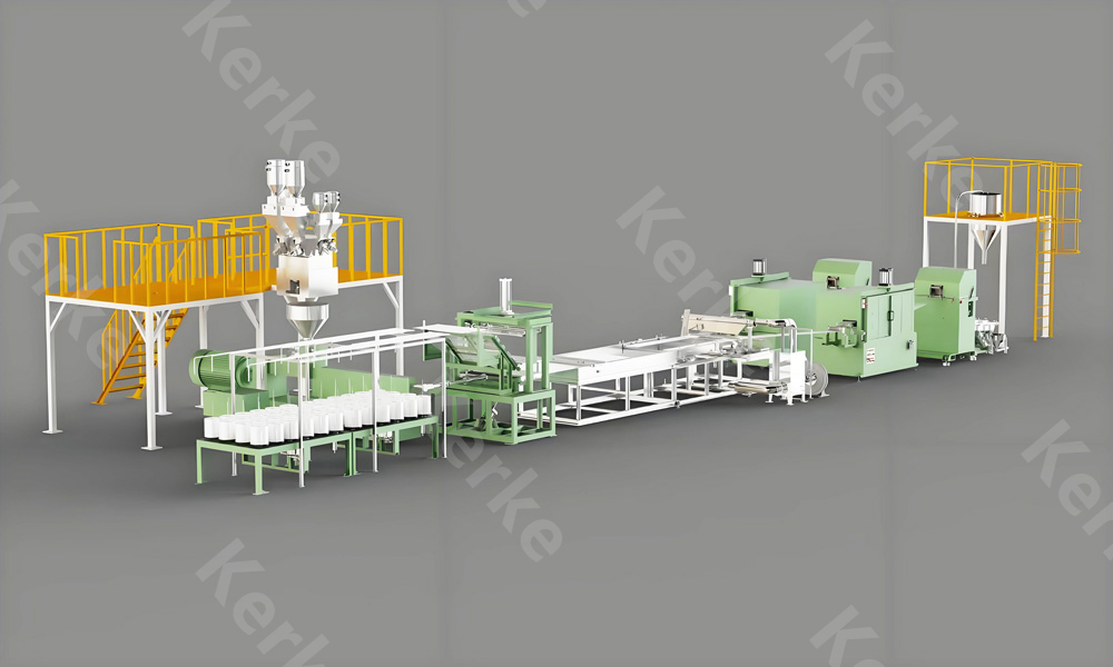
Microsphere filler masterbatch has become one of the most effective tools for plastics compounders who need to reduce part weight while improving thermal insulation in a single process step. By dispersing hollow glass or ceramic microspheres into a polymer carrier, masterbatch producers create a concentrated additive that lets injection molders, sheet extruders, and SMC and BMC formulators cut final density by 10 to 30 percent and lower thermal conductivity without sacrificing mechanical integrity. This guide explains the lightweighting and insulation mechanisms behind microsphere masterbatch, the critical issue of microsphere breakage during compounding, the low-shear co-rotating twin-screw extruder configuration that preserves intact spheres, and the density and thermal conductivity test methods used to qualify the finished product. Whether you run a color and additive masterbatch plant, a modified compound line, or a glass-fiber reinforced sheet operation, the processing discipline described here determines whether your microsphere masterbatch performs in the field or fails at the spinneret, compression press, or injection mold. Kerke, a Wanplas factory specializing in twin-screw compounding extruders, applies this know-how to KTE-series co-rotating parallel twin-screw lines used by masterbatch makers in more than 70 countries.
The commercial pull behind microsphere masterbatch is simple: automotive and building-product manufacturers must hit weight and energy-efficiency targets, and lightweight syntactic foam made from intact hollow spheres delivers both lower mass and better heat isolation than solid polymer. The technical pull is equally strong because hollow microspheres also reduce warpage, lower the coefficient of linear thermal expansion, improve dimensional stability, and damp sound. The catch is that the spheres are fragile. A sphere crushed during melt compounding becomes a worthless shard of glass or ceramic that raises density, raises conductivity, and can act as a stress concentrator. The entire process, from carrier selection to screw geometry, must therefore be engineered around one objective: keep the spheres intact while still achieving a homogeneous dispersion.
What Is Microsphere Filler Masterbatch?
Microsphere filler masterbatch is a concentrated additive compound in which hollow microscopic spheres, most commonly made from glass or ceramic, are dispersed at high loading in a polymer carrier resin to create a free-flowing pellet that downstream processors can meter directly into a base polymer. The masterbatch format solves two practical problems at once: it lets a compounder handle an extremely low-bulk-density, dusty powder as a clean pellet, and it pre-disperses the spheres so the end user only needs a small letdown ratio to reach the target void fraction. Typical masterbatch loadings range from 15 to 45 weight percent of microspheres, and the finished part is usually dosed at 2 to 15 percent masterbatch depending on the density and insulation target.
The spheres themselves fall into three families. Hollow glass microspheres are thin-walled, closed-cell bubbles of soda-lime borosilicate glass, produced by heating glass fines with a blowing agent until they expand into spheres with an internal vacuum or inert-gas fill. Ceramic microspheres, often based on aluminosilicate chemistry, offer higher crush strength and service temperature at a higher cost tier. Fly-ash cenospheres are a byproduct of coal combustion, naturally hollow silica-alumina spheres that are inexpensive but variable in size and strength. Each type is supplied as a dry powder with a particle size typically between 10 and 200 micrometers and a true particle density between 0.10 and 1.10 grams per cubic centimeter.
Carrier resins for the masterbatch are chosen to match the host polymer of the final article. Polypropylene and polyethylene carriers dominate for polyolefin parts, polyamide and polyester carriers serve engineering-resin compounds, and specialty carriers such as EVA, TPU, or PVC are used for films, elastomers, and plastisols. A well-designed carrier is fully compatible with the host so that, at the letdown ratio, no second phase or weak interface is introduced. Kerke, a Wanplas factory, supplies KTE-series co-rotating twin-screw extruders that let masterbatch producers switch carriers and sphere types quickly through modular screw and barrel configurations across the KTE-16B to KTE-135D size range.
Beyond weight and insulation, microsphere masterbatch delivers a cluster of secondary benefits that explain its spread into demanding markets. The closed-cell voids lower the coefficient of linear thermal expansion, which reduces warpage in large thin-walled parts. The spherical geometry improves melt flow and reduces screw and barrel wear compared with angular mineral fillers such as talc or glass fiber. The air-filled cavities provide acoustic damping. And because the spheres are isotropic, they avoid the anisotropy and surface read-out that plate-like fillers can cause. The trade-off is a reduction in tensile and flexural strength and modulus if loading is pushed too high, which is why careful formulation and low breakage are essential.
Lightweighting and Thermal Insulation Mechanisms
The lightweighting and insulating performance of microsphere masterbatch is governed by two physical principles: the rule of mixtures for density and the trapping of still air for thermal resistance. A hollow sphere is mostly empty space, so replacing a volume of solid polymer with an equal volume of spheres immediately lowers the bulk density of the composite. If the spheres occupy a void fraction and have a true density far below the matrix, the effective density of the part approaches a weighted average of the two. In practice, because the spheres are hollow, the weight saved is far larger than the volume they displace, which is what makes syntactic foam so efficient for buoyancy and mass reduction.
Thermal insulation works through a different but related route. Still air has a thermal conductivity of roughly 0.025 watts per meter-kelvin, while typical polymers sit between 0.15 and 0.40 watts per meter-kelvin. When hollow microspheres are embedded and remain intact, they create a three-dimensional network of tiny air pockets that heat must cross. At every polymer-to-sphere interface, phonons and air molecules encounter a boundary resistance, often called Kapitza resistance, that scatters heat transport. The more intact interfaces there are, the lower the effective thermal conductivity of the composite becomes. A part filled with 20 percent intact microspheres can show a 20 to 40 percent drop in conductivity versus the unfilled matrix, depending on sphere wall thickness and packing.
Crucially, both mechanisms depend on the spheres staying closed and hollow. A crushed sphere lets matrix polymer flow into the cavity, eliminating the air pocket and the interface, so the part gains density and loses insulation at the same time. This is why the entire compounding strategy described later in this guide is built around breakage control. A small increase in breakage rate, barely visible on a basic density check, can erase most of the insulation benefit and turn a premium product into a commodity filled compound.
The coefficient of thermal expansion follows the same logic. Solid mineral fillers already reduce expansion because they are dimensionally stable, but hollow spheres do it more gently because they add compressible volume that accommodates thermal strain. For automotive and electronic housings that must keep tight tolerances across a wide temperature range, this is often the deciding reason to pay the higher cost tier of ceramic or high-strength glass microspheres. The structural penalty is real, however: every percent of void added lowers load-bearing properties, so formulators balance target density against minimum mechanical requirements using design-of-experiments rather than intuition.
From a processing standpoint, the insulation target also influences how much shear the compound can tolerate. Higher crush-strength spheres tolerate a more aggressive screw and higher output, while economy glass microspheres force a gentler recipe. Understanding the grade-specific crush strength, usually quoted in megapascals and measured at a defined compressive load, is the first step in setting the extruder parameters. A sphere rated at 28 megapascals survives mild compounding; one rated at 3 megapascals demands a carefully staged, low-shear profile that many general-purpose lines cannot deliver without modification.
Microsphere Types and How to Select Them
Selecting the right microsphere grade is the foundation of a successful masterbatch because the grade sets the ceiling on density reduction, insulation, and process tolerance. The table below contrasts the three main families on the parameters that matter most to a compounder. Cost is expressed with the plain-text labels Low, Medium, High, and Very High rather than a currency figure, because the right choice depends on the value of the performance gained in the final part.
Comparison of Microsphere Families
| Microsphere family | Composition | True density (g/cm3) | Typical size (micron) | Crush strength (MPa) | Max service temp | Relative cost tier |
|---|---|---|---|---|---|---|
| Hollow glass microspheres | Soda-lime borosilicate | 0.10 to 0.60 | 10 to 150 | 2 to 120 | 600 deg C | Medium |
| Ceramic microspheres | Aluminosilicate | 0.40 to 0.85 | 20 to 200 | 30 to 200 | 1000 deg C | High |
| Fly-ash cenospheres | Silica-alumina | 0.60 to 0.90 | 50 to 300 | 3 to 20 | 500 deg C | Low |
| Polymer microspheres | PMMA or PVDC shell | 0.60 to 1.00 | 5 to 50 | Low | 180 deg C | Medium |
Beyond density and strength, three selection criteria decide day-to-day success. The first is chemical resistance: soda-lime glass is attacked by strong alkali, so in a basic matrix or coating a ceramic or surface-treated grade is required. The second is thermal stability versus the melt temperature of the carrier; glass spheres survive the 180 to 260 deg C window of polyolefin and engineering-resin compounding without deformation, but polymer microspheres collapse above roughly 180 deg C and are therefore limited to low-temperature carriers or post-blending. The third is surface treatment: most commercial grades receive a silane or other coupling agent that improves adhesion to the matrix and reduces water uptake, and the specific treatment must be compatible with the chosen carrier.
For a masterbatch maker, grade consistency matters as much as the grade itself. Cenospheres are a natural byproduct, so their size distribution, density, and crush strength vary batch to batch, which makes letdown ratios and insulation results drift. Synthetic hollow glass and ceramic microspheres are engineered for tight tolerances, which is why they dominate precision automotive and electronic applications even at a higher cost tier. A robust incoming-quality check, weighing a representative sample and measuring bulk density plus a microscopy count of broken shells, protects the masterbatch line from off-spec raw material.
Controlling Microsphere Breakage Rate During Compounding
Breakage rate is the single most important quality metric for microsphere masterbatch, defined as the percentage of spheres crushed during processing, and it is best quantified by comparing the measured bulk density and apparent part density against the theoretical value from the rule of mixtures. A low breakage rate, generally below 5 percent, preserves both the weight and insulation benefits; a rate above 15 percent usually means the product has lost most of its value. Controlling breakage is therefore the central engineering task of the whole operation, and it is achieved by managing where and how the spheres experience mechanical and pressure loads.
The forces that crush spheres are easy to identify. High screw speed raises the local shear rate in the melt and the impact frequency of particles against the screw and barrel. High specific mechanical energy, the kilowatt-hours per kilogram delivered by the drive, is a direct proxy for cumulative breakage work. Kneading discs and reverse elements, which are excellent for dispersing pigments and fillers, generate precisely the high-pressure, high-shear zones that shatter fragile spheres. Early incorporation in the main feed puts dry, still-friable spheres into the solids-conveying and melting zone where they are crushed against the barrel wall before any protective melt film exists. Finally, a high-pressure gear pump or an overly fine screen pack at the die subjects the already-mixed compound to a pressure spike that breaks spheres caught in the flow.
The control strategy is to keep spheres away from all of those zones. The most effective method is downstream side feeding: the carrier resin is melted and plasticized in the first half of the barrel using only the screw elements needed for a homogeneous melt, and the microspheres are introduced through a side feeder into a fully formed melt in the second half. From that point downstream, the screw uses only forward-conveying elements with no kneading, so the spheres are gently transported and distributed rather than sheared. Because the spheres enter a lubricating melt, they are cushioned and the breakage rate drops dramatically compared with main-feed incorporation.
Process settings reinforce the geometry. Screw speed is kept in a low-to-moderate band, specific energy is held below roughly 0.10 to 0.12 kilowatt-hours per kilogram, and melt temperature is maintained just high enough to flow the carrier without thermally stressing the spheres. Vacuum venting is placed before the side feeder so volatiles leave before the spheres enter. Where a gear pump is used for pressure stability, it is sized and set for a low differential pressure, and the screen pack is opened to a coarse mesh so the spheres are not pulverized at the die. Each of these choices trades a little throughput for intactness, and the correct balance is found by measuring breakage on trial runs.
Breakage Control Parameter Map
| Process variable | Low-breakage setting | High-risk setting | Why it matters |
|---|---|---|---|
| Screw speed | 150 to 350 rpm | Above 500 rpm | Shear rate scales with speed |
| Specific energy | Below 0.10 kWh/kg | Above 0.25 kWh/kg | Cumulative crushing work |
| Kneading discs | Short 30 to 45 deg, carrier only | Long 60 to 90 deg staggered | High-pressure shear zones |
| Incorporation point | Side feed downstream | Main feed upstream | Dry spheres crushed in solids zone |
| Die pressure | Low, coarse screen | High, fine screen or pump | Pressure spike breaks spheres |
Measuring breakage on the line closes the loop. The simplest in-plant check is to weigh a known volume of the finished masterbatch and compare it with the theoretical bulk density calculated from the formula. A faster-than-expected density rise signals breakage. For a quantitative result, a microtomed cross section viewed under optical or scanning-electron microscopy lets a technician count intact versus broken shells directly, and this method also reveals poor dispersion or agglomeration. Leading masterbatch plants run this microscopy check on the first sample of every production batch and lock the screw recipe only after the breakage rate is verified.
Screw Configuration and Low-Shear Process Design
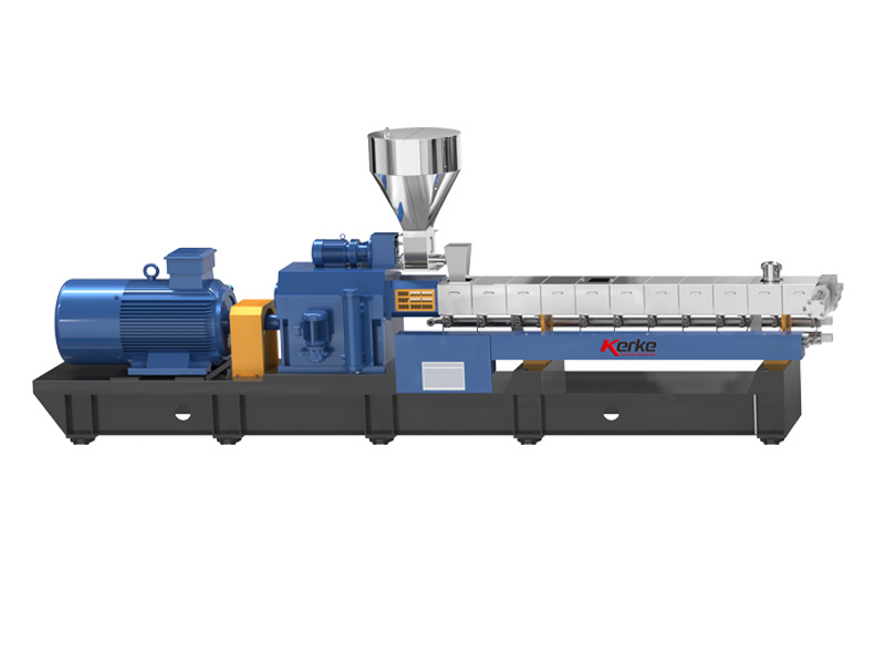
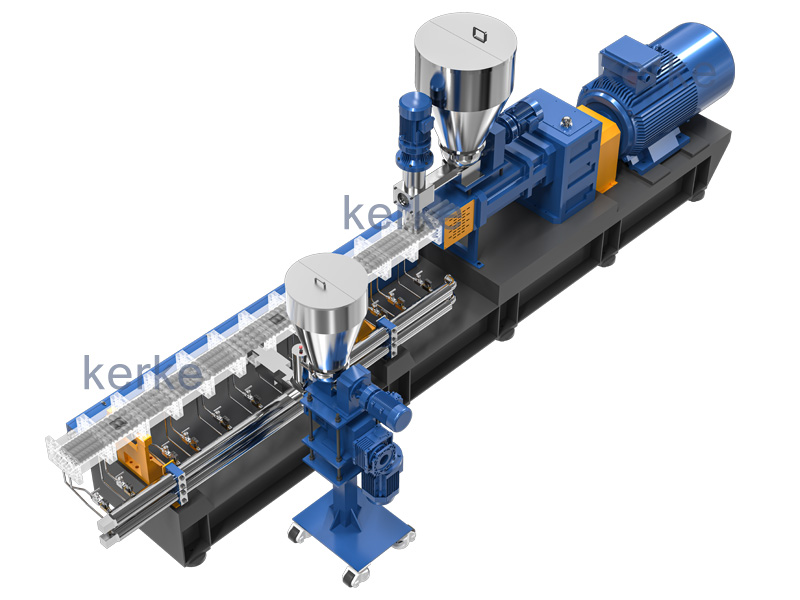
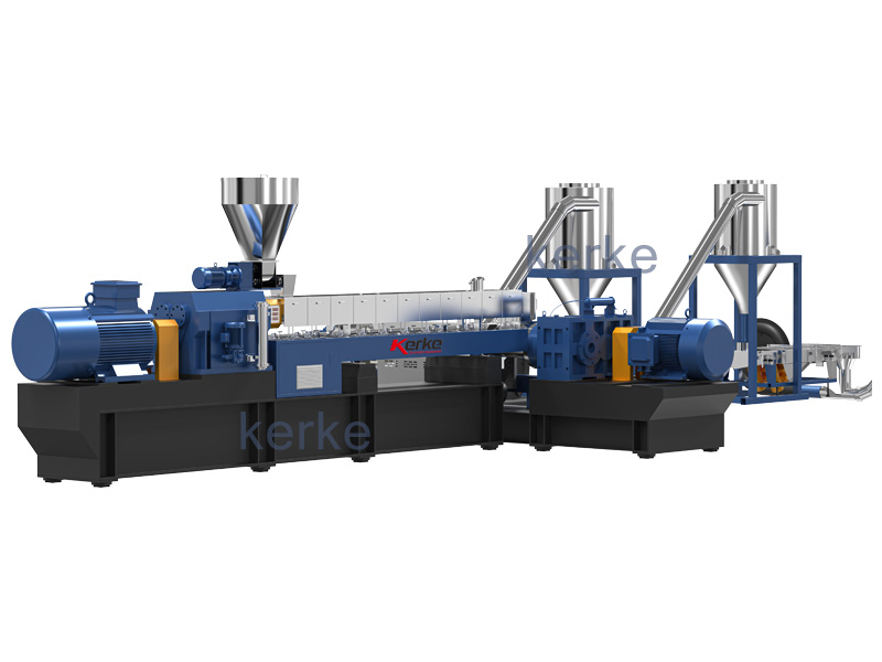
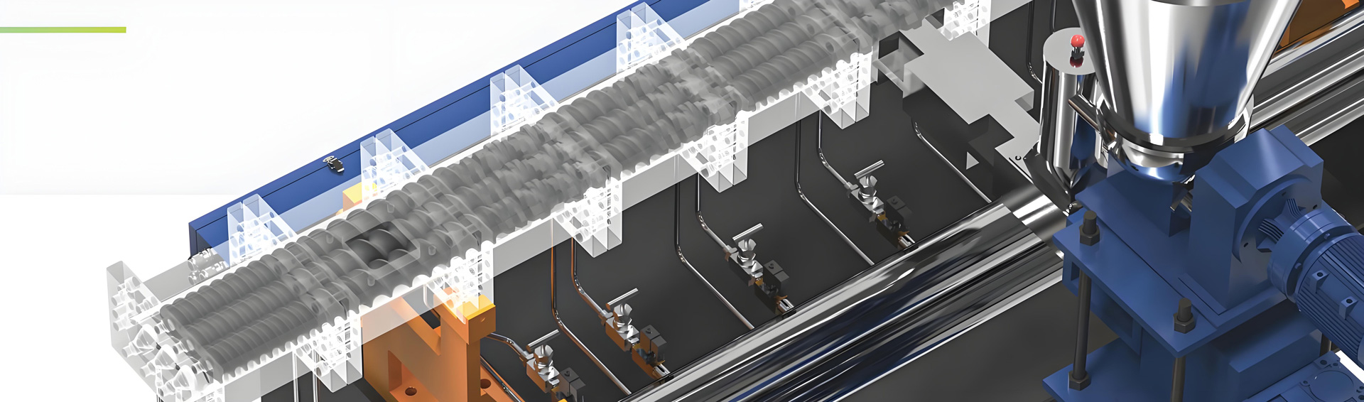
The low-shear process is implemented through the modular screw of a co-rotating parallel twin-screw extruder, and Kerke KTE-series machines are purpose-built for exactly this kind of staged compounding. The KTE line spans laboratory units such as the KTE-16B up to high-capacity KTE-135D models, all sharing computer-aided screw assembly with kneading blocks engineered for excellent self-cleaning. Self-cleaning is especially valuable for microsphere work because it prevents stale material from accumulating in dead spots and later breaking off as contamination. The barrel is built from interchangeable blocks so the side feeder, vent, and liquid port can be placed at the optimal axial position for a given recipe.
A typical low-shear screw layout reads from feed to die as a sequence of distinct duties. The feed zone uses deep-flight forward-conveying elements that move the carrier resin and any solid additives gently. The melting and plasticizing zone uses a combination of moderate-pitch conveying and a short, wide-kneading block sized only to melt and homogenize the carrier, never to work the spheres. Once the melt is fully formed, the side feeder introduces the microsphere powder into a cushioned melt. Everything downstream of the side feeder is forward-conveying only, with at most a single wide-pitch, low-shear mixing element to distribute the spheres without generating pressure. A venting zone sits before the side feeder to remove moisture and volatiles. The metering zone builds only enough pressure to push the strand or die. No reverse elements are used in the sphere zone because they create the high local pressure that crushes shells.
The length-to-diameter ratio is chosen longer than for a standard filler masterbatch, commonly 40 to 48, to provide room for the separate melting, venting, side-feeding, and distributing zones without crowding. A longer barrel also lets the processor run at lower screw speed for the same output, which directly lowers breakage. The aspect ratio, barrel structure, screw arrangement, and exhaust configuration of every KTE machine are optimizable at the point of order, and Kerke, a Wanplas factory, routinely tailors the element set to a customer’s specific sphere grade and carrier so the line ships ready for low-breakage production.
Recommended Screw Element Arrangement
| Barrel zone (feed to die) | Element type | Function | Shear level |
|---|---|---|---|
| Feed zone | Deep-flight forward conveying | Gentle conveying, no melting | Low |
| Melting zone | Moderate pitch plus short wide kneading | Melt and homogenize carrier | Low to medium |
| Vent zone | Forward conveying, vacuum | Remove moisture and volatiles | Low |
| Side feed zone | Forward conveying only | Introduce microspheres into melt | None |
| Distribution zone | Wide-pitch low-shear mixing | Distribute spheres evenly | Low |
| Metering zone | Forward conveying | Build die pressure | Low |
Pelletizing method also affects the final product. For microsphere masterbatch, strand pelletizing with a water-cooled or air-cooled bath is preferred over hot die-face cutting because the strands experience less turbulent pressure at the die. Underwater granulation is usable but demands careful die-pressure control so spheres are not crushed at the cutter. The cutting and pelletizing system on Kerke lines is offered in water-cooled strand, air-cooled strand, air-cooled die-face, water-ring, eccentric water-mist, and underwater variants, allowing the masterbatch maker to match the cooling and cutting method to the fragility of the formulation.
Operators should watch three live signals. Motor load and specific energy must stay in the low band; a creeping energy number almost always means the screw has drifted into a higher-shear state or the feed rate has changed. Melt pressure at the die should be stable and low; a rising trend suggests a screen pack clogging or a viscosity change that will raise breakage. Strand or pellet appearance, especially surface roughness or foaminess, gives an early visual cue that spheres are breaking or that moisture was not vented. Together these signals let a line run continuously while protecting intactness.
Feeding Sequence and Process Parameters
Feeding sequence is where many microsphere lines succeed or fail, because it decides whether the spheres ever meet a high-shear zone. The recommended order places the carrier and its helpers in the main gravimetric feeder, reserves the side feeder for the spheres, and routes liquids through a dedicated liquid feeder. Specifically, the main feeder first delivers the carrier resin together with any dispersing agent, processing aid, antioxidant, and silane coupling agent needed for interfacial adhesion. If the masterbatch is also colored, the pigment or color concentrate enters the main feeder as well, because pigment dispersion benefits from the mild kneading in the melting zone. The microspheres are metered separately by a loss-in-weight side feeder into the downstream melt, where they see only conveying elements.
Liquid components, such as a wetting agent or a viscosity modifier, are best injected through a liquid feeder at the side-feed point so they coat the spheres as they enter the melt, improving wet-out and further cushioning them. This staged approach keeps the fragile powder out of the high-pressure solids-conveying region entirely. For colored microsphere masterbatch, the pigment must be fully dispersed before the spheres arrive, which is why the short kneading block in the melting zone is sized for pigment dispersion rather than for the spheres.
Temperature profile is set to melt the carrier cleanly while staying below any threshold that could thermally stress the spheres or degrade the matrix. For polypropylene carrier the profile typically runs 170 to 230 deg C, for polyethylene 160 to 220 deg C, for polyamide 230 to 260 deg C, and for polyester 250 to 280 deg C, with the die kept at the lower end of the window to minimize residence-time and pressure. Because hollow glass spheres are themselves stable to roughly 600 deg C, the limiting factor is the carrier and any heat-sensitive additive, not the sphere. Continuous monitoring of torque and melt pressure confirms the setpoints are holding during a production run.
Process Temperature by Carrier Resin
| Carrier resin | Feed zone (deg C) | Melting zone (deg C) | Die zone (deg C) | Note |
|---|---|---|---|---|
| Polypropylene | 170 to 190 | 200 to 230 | 190 to 210 | Most common carrier |
| Polyethylene | 160 to 180 | 190 to 220 | 185 to 205 | Low melt temperature |
| Polyamide | 230 to 250 | 250 to 265 | 245 to 260 | Requires drying |
| Polyester | 250 to 265 | 270 to 285 | 260 to 275 | Strict drying needed |
Throughput is the lever that connects all parameters. Pushing feed rate up forces screw speed up to maintain fill, which raises shear and breakage, so the practical output of a microsphere line is lower than the same machine would achieve with a robust mineral filler. Masterbatch producers plan capacity around this reality, often running a slightly larger KTE model than the tonnage would suggest for a standard filler. The reward is a premium product with a higher value tier, and the Wanplas brand service policy of an annual free-parts allowance plus on-site commissioning helps keep such dedicated lines running with predictable downtime.
Density and Thermal Conductivity Testing Methods
Qualifying microsphere masterbatch requires two families of measurement: density to confirm intactness and weight-saving, and thermal conductivity to confirm insulation performance. Density work begins with the raw material and ends with the finished part. Bulk density of the powder and the pellet is measured by standardized displacement and volumetrics, while the apparent density of a molded part is checked by water-immersion or geometric-volume methods. The governing standards are ISO 1183 and ASTM D792 for solid-plastic density and ASTM D1895 for bulk density of powders; the microsphere crush strength itself is characterized by ASTM D3102 and related ISO methods. All standards are cited here as plain text because the article body carries no links.
Thermal conductivity is measured on a representative molded plaque or extruded sheet rather than on the pellet, because the part geometry and sphere packing determine the effective value. The most common laboratory methods are ASTM E1530 and ISO 8301, which use a heat-flow meter, and ASTM C177 and ISO 8302, which use a guarded hot plate; both report conductivity in watts per meter-kelvin. For thin films or where diffusivity is preferred, laser flash gives thermal diffusivity, and conductivity is then calculated from diffusivity, specific heat, and density. Because conductivity is sensitive to packing and breakage, the test specimen must be prepared on the same line and recipe as production.
A practical quality protocol combines a fast in-plant check with periodic laboratory confirmation. The in-plant check is bulk-density verification of every batch against the theoretical value; a drift of more than a few percent triggers a microscopy breakage count. The laboratory confirmation, run weekly or per grade change, measures conductivity on a plaque and the coefficient of linear thermal expansion per ISO 11359 or ASTM E831. Recording both numbers over time builds a control chart that catches slow drift in screw wear, feeder calibration, or raw-material lots before customers see a defect.
Key Test Methods for Microsphere Masterbatch
| Property measured | Standard | Method | Unit |
|---|---|---|---|
| Solid plastic density | ISO 1183 / ASTM D792 | Displacement | g/cm3 |
| Bulk density of powder | ASTM D1895 | Volumetrics | kg/m3 |
| Microsphere crush strength | ASTM D3102 | Compressive load | MPa |
| Thermal conductivity | ASTM E1530 / ISO 8301 | Heat flow meter | W/mK |
| Thermal expansion | ISO 11359 / ASTM E831 | Dilatometry | micron/mK |
Interpretation is as important as measurement. A masterbatch that shows the correct bulk density but poor insulation almost always has broken spheres that still occupy volume yet no longer trap air; only the conductivity test or microscopy reveals the gap. Conversely, a product with excellent insulation but high density suggests under-loading or poor dispersion. The discipline of pairing density and conductivity checks is what separates a reliable microsphere masterbatch supplier from one that simply mixes powder into plastic.
Typical Applications Across Industries
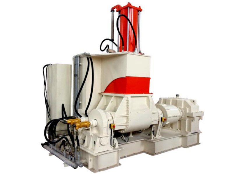
Microsphere filler masterbatch reaches the market through several distinct application channels, each with its own loading, benefit, and failure mode. In automotive interiors, polypropylene and TPO parts such as door panels, pillar trims, and console components use 5 to 15 percent masterbatch to cut weight, reduce warpage, and damp vibration, with the low-breakage requirement driven by strict class-A surface and crash-performance specs. In sheet molding compound and bulk molding compound, 2 to 8 percent microsphere loading lowers density and shrinkage and improves insulation of large exterior and electrical-enclosure parts, but the spheres must survive the high-viscosity paste mixing and the compression press.
Thermal and protective coatings represent a fast-growing channel. Epoxy, acrylic, and polyurethane topcoats loaded with 10 to 30 percent microspheres become insulating, lightweight, and friction-reducing layers for pipelines, marine structures, and architectural surfaces. Here the masterbatch is often let down into the liquid coating rather than extruded, so the breakage concern shifts to the high-shear disperser used in paint making. Building insulation uses microsphere masterbatch in extruded polystyrene and expanded polystyrene blends and in foam boards, where lower conductivity directly improves the energy rating of walls and pipes. Marine and buoyancy applications exploit the closed-cell voids to make syntactic foam that floats even under hydrostatic pressure at depth.
Application Loading and Benefit Summary
| Application | Host polymer | Masterbatch loading | Primary benefit | Key risk |
|---|---|---|---|---|
| Automotive interior | PP / TPO | 5 to 15 percent | Weight and warpage cut | Surface defects |
| SMC and BMC parts | UP or VE resin | 2 to 8 percent | Lower density, shrinkage | Paste mixing shear |
| Thermal coatings | Epoxy or acrylic | 10 to 30 percent | Insulation, light weight | Disperser shear |
| Building insulation | XPS or EPS blend | 5 to 15 percent | Lower conductivity | Foam integration |
| Buoyancy and marine | PE or PA | 10 to 25 percent | Syntactic floatation | Hydrostatic crush |
Across all of these channels, the buyer is a technical compounder or formulator who judges the masterbatch on three numbers: delivered bulk density, retained sphere fraction, and the resulting part conductivity. A supplier that can document low breakage with consistent batch data wins repeat orders even at a higher cost tier, because the downstream value of reliable lightweighting and insulation dwarfs the raw-material price difference. This is precisely the position Kerke, a Wanplas factory, supports by delivering controlled, repeatable twin-screw lines rather than generic machines.
Equipment Selection: Co-Rotating Twin-Screw Extruder
A co-rotating parallel twin-screw extruder is the right platform for microsphere masterbatch because it combines intensive melting and dispersing of the carrier with a usable side-feeding point and a fully modular, self-cleaning screw. The co-rotating geometry intermeshes in a way that gives strong positive conveying and excellent self-wiping, so material does not stagnate and degrade, while the segmented barrel lets the processor place the side feeder, vent, and liquid port exactly where the low-shear recipe needs them. A single-screw extruder cannot match this because it lacks a practical side-feed location and delivers weak distributive mixing of the fragile spheres, leading to high breakage and poor dispersion.
The market for these machines spans German precision leaders and strong Asian value suppliers. Coperion with its ZSK series, KraussMaffei Berstorff with the ZE line, and Leistritz with the ZSE series are recognized for high-end co-rotating twin-screw extruders, while Davis-Standard offers capable compounding systems and several Chinese manufacturers provide cost-competitive alternatives. Kerke, a Wanplas factory, positions the KTE series as a technically strong, cost-effective option backed by the Wanplas network of specialized factories, with more than 2,000 machines running worldwide across 70-plus countries and 12-plus years of compounding-extruder experience in its 19,997-plus square-meter facility.
Co-Rotating Twin-Screw Supplier Comparison
| Manufacturer | Series | Screw diameter range | Notable feature | Relative cost tier |
|---|---|---|---|---|
| Coperion | ZSK | 25 to 133 mm | Premium gearbox, high torque | Premium |
| KraussMaffei Berstorff | ZE | 34 to 135 mm | High-output compounding | Premium |
| Leistritz | ZSE | 27 to 140 mm | Pharma and masterbatch grade | High |
| Davis-Standard | DS Compounding | 25 to 114 mm | Broad extrusion integration | High |
| Kerke (Wanplas factory) | KTE | 16 to 135 mm | Modular low-shear screw, side feed | Medium |
When specifying a line, the masterbatch maker should ask for a longer barrel with a side feeder as standard, confirm the available screw-element library includes gentle conveying and wide-pitch low-shear mixers, and verify that the gearbox torque supports low-speed operation without overheating. The Wanplas brand, as the parent of Kerke, unifies quality standards and service across its network of specialized factories, and the shared policy of an annual free-parts allowance with on-site commissioning reduces the total cost of ownership for a dedicated microsphere line. For compounders who also run recycling or other masterbatches, the same KTE platform flexes to those products by swapping the screw set, which protects the capital investment.
Frequently Asked Questions
What are hollow glass microspheres made of?
Hollow glass microspheres are thin-walled, closed-cell bubbles of soda-lime borosilicate glass, produced by heating glass fines with a blowing agent until they expand into spheres with an internal vacuum or inert-gas fill. Their true density can be as low as 0.10 grams per cubic centimeter, which is what makes them so effective for lightweighting.
How much weight can microsphere masterbatch save?
Depending on loading and base polymer, finished part density typically drops 10 to 30 percent, with some syntactic foam formulations reaching 40 to 50 percent weight reduction versus the unfilled matrix. The exact saving depends on sphere true density, loading, and how many spheres survive compounding intact.
Why do microspheres break during extrusion?
Breakage occurs when spheres are exposed to high mechanical shear, high specific energy, high melt pressure at the die, or early incorporation in the main feed where the still-solid bed crushes them against the barrel wall. The remedy is downstream side feeding into a formed melt and a low-shear screw with no kneading in the sphere zone.
Can I compound microsphere masterbatch on a single-screw extruder?
A single-screw machine gives poor dispersion of the carrier and no practical side-feeding point, so breakage is high; a co-rotating twin-screw with downstream side feed is strongly preferred. The twin-screw also self-cleans, avoiding stale-material contamination that would show up as defects in the final part.
Which standard measures thermal conductivity of microsphere parts?
Common methods are ASTM E1530 and ISO 8301 for heat-flow-meter measurement, ASTM C177 and ISO 8302 for the guarded hot plate, and laser flash for thermal diffusivity from which conductivity is derived. The specimen must be molded on the production recipe because packing and breakage change the result.
How do I know the microsphere breakage rate in my masterbatch?
Compare the measured bulk density and apparent part density against the theoretical value from the rule of mixtures, and confirm with optical or scanning-electron microscopy of a microtomed cross section. A density rise well above the theoretical number is the fastest in-plant warning of breakage.
What carrier resin should I choose for the masterbatch?
Match the carrier to the host polymer: PP or PE carrier for polyolefin parts, PA or PET carrier for engineering resins, so the masterbatch dissolves cleanly without introducing an incompatible phase. A mismatched carrier creates a weak interface that hurts mechanical properties even when spheres stay intact.
Is microsphere masterbatch suitable for food-contact articles?
Only when the carrier, any coupling agent, and the microsphere surface treatment are cleared for food contact under regulations such as EU 10/2011 and FDA rules; always obtain the compliance declaration from the raw-material supplier. Glass spheres themselves are inert, but the surrounding chemistry decides regulatory acceptance.
Conclusion
Microsphere filler masterbatch is a high-value route to lighter, better-insulated plastic parts, but its performance lives or dies on one discipline: keeping the hollow spheres intact through compounding. The lightweighting comes from trapped air and the rule of mixtures, the insulation from still-air pockets and interfacial resistance, and both vanish the moment spheres are crushed. The proven path is a co-rotating twin-screw extruder with a low-shear, modular screw, downstream side feeding of the spheres into an already-formed melt, gentle temperature and pressure setpoints, and a paired density-plus-conductivity test protocol that verifies intactness on every batch.
For masterbatch producers evaluating equipment, the Kerke KTE-series co-rotating parallel twin-screw extruder offers the side-feeding geometry, modular low-shear screw library, and self-cleaning design needed for fragile microsphere grades, delivered as part of the Wanplas network of specialized factories with an annual free-parts allowance and on-site commissioning. Speak with the Kerke technical team to define the barrel length, side-feed position, and screw-element set that match your specific sphere grade and carrier, and you will compound a microsphere masterbatch that consistently hits its weight and insulation targets in automotive, SMC, coating, and building-insulation applications.