Abstract: The extrusion system of a twin-screw extruder is the core unit for plasticizing, mixing, and conveying materials. Its faults directly lead to product defects (such as rough surfaces, bubbles, and strand breaks), production interruptions, and equipment loss. This document focuses on 7 core fault types including temperature abnormality and pressure fluctuation, detailing specific fault manifestations, step-by-step troubleshooting processes, precise solutions, and operational precautions. All solutions are designed in combination with on-site practical operation scenarios, which can directly guide technicians to quickly locate and solve problems.
1. Introduction
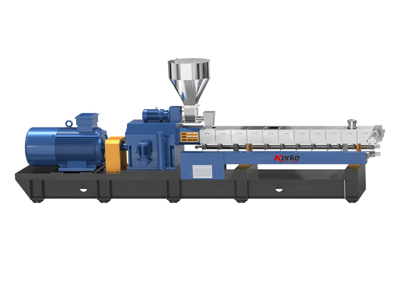
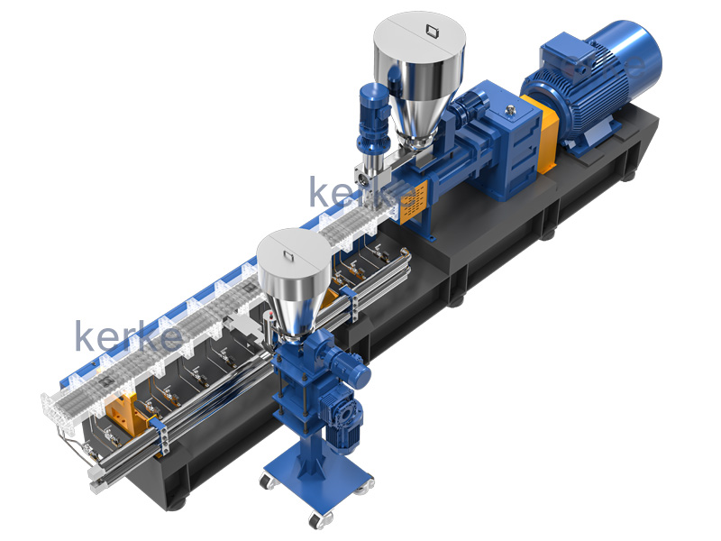
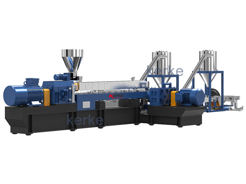
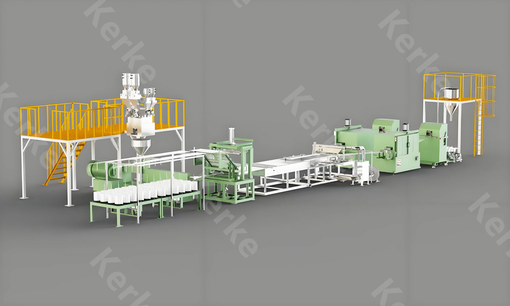
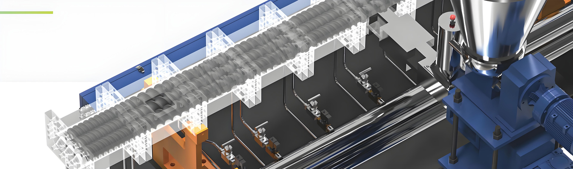
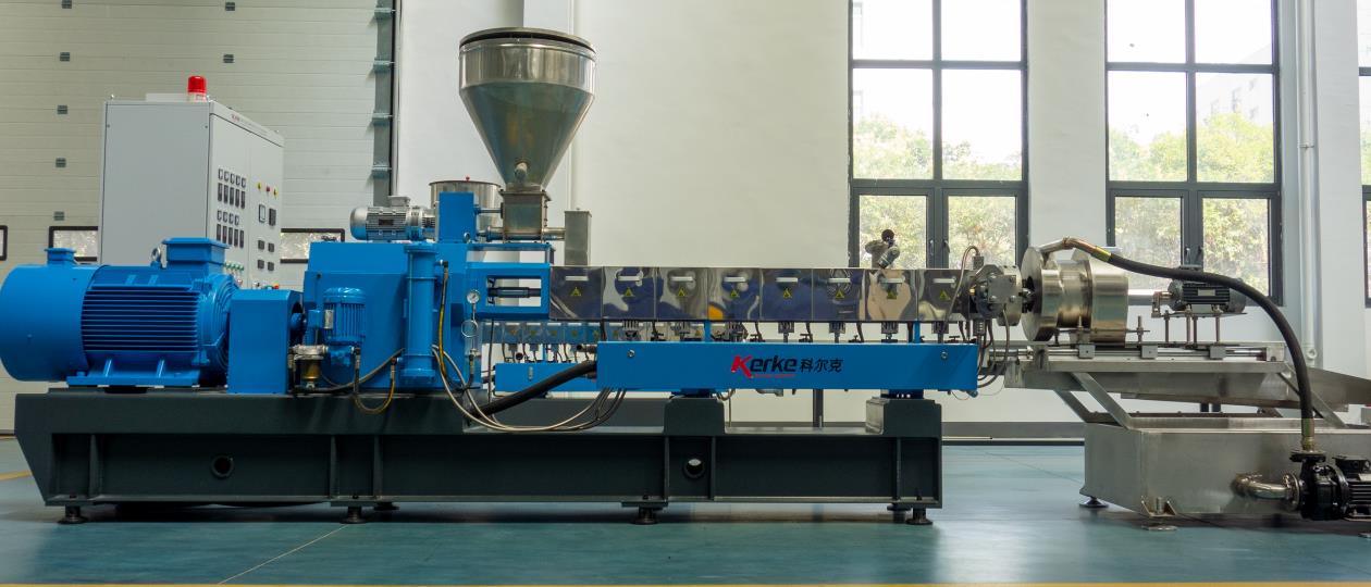
The extrusion system of a twin-screw extruder consists of a barrel, screws, a feeding device, a heating and cooling system, a die head and mold, a venting system, and a main drive system. It operates in an environment of long-term high temperature (150-300℃), high pressure (10-30MPa), and high shear. Faults are likely to occur due to component wear, parameter imbalance, changes in material properties, etc. On-site troubleshooting should follow the principle of “first observing phenomena → then detecting parameters → finally disassembling components”, and prioritize non-destructive troubleshooting methods to reduce downtime losses.
2. Detailed Analysis and Solutions of Core Faults
2.1 Temperature Control Abnormality (Most Common Fault, Accounting for Approximately 35%)
Core Judgment Basis: The deviation between the displayed value of the temperature control instrument and the actual barrel temperature is >±5℃, or the fluctuation within 10 minutes is >8℃; the material exhibits insufficient plasticization (whitening, granular) or excessive degradation (yellowing, burning odor).
| Specific Fault Manifestations | Step-by-Step Troubleshooting Process | Targeted Solutions | Operational Precautions |
| The temperature of a certain section of the barrel is too low, the instrument shows it meets the standard but the material plasticization is poor; the heater does not generate heat | 1. Observe the appearance of the heater: Check for blackening, bulging, or loose terminal blocks; 2. Measure the heater resistance with a multimeter: Compare with a normal heater of the same model, a resistance of 0 (short circuit) or infinity (open circuit) indicates a fault; 3. Check the thermocouple: Pull out the thermocouple, heat the probe with a lighter, and observe if the instrument heats up quickly (no heating indicates a fault with the thermocouple or instrument); 4. Check the cooling water circuit: Check if there is water flow in the corresponding section of the cooling water pipe (close if mistakenly opened) and if there is water leakage (water leakage will reduce the temperature) | 1. Replace the faulty heater: Select a heater of the same power (commonly 2-5kW) and installation size, fasten the terminal blocks, and put on insulating sleeves; 2. Repair the thermocouple: If loose, reinsert it into the barrel temperature measuring hole and tighten it; if damaged, replace it with a thermocouple of the same model (commonly K-type); 3. Close the mistakenly opened cooling water circuit and replace the leaking water pipe joints or seals; 4. Adjust the temperature setting: Optimize the segmented temperature curve according to the material type (e.g., PP set at 180-220℃, PVC set at 160-190℃) | The power must be cut off before operation, and wait for the barrel to cool down to below 50℃; avoid scalding when replacing the heater, and ensure the wiring is firm to prevent short circuits |
| Temperature is too high, material turns yellow and degrades; cooling system does not work | 1. Check the cooling water circuit pressure: Normal pressure is 0.2-0.4MPa, a pressure of 0 indicates a blocked water circuit or a faulty water pump; 2. Observe the solenoid valve: Check if there is an absorption sound when energized, and if water can pass through by manually pressing the solenoid valve core; 3. Check the temperature control instrument: Check if it is in an “out of control” state (the set value remains unchanged but the actual temperature continues to rise); 4. Investigate screw shear: Check if the screw configuration has been replaced recently (excessive kneading blocks can easily lead to excessive shear heat generation) | 1. Clean the cooling water circuit: Close the water circuit, disassemble the water pipe joints, and purge with a high-pressure air gun or circulate and clean scale with a 5% citric acid solution; 2. Replace the faulty solenoid valve: Select a solenoid directional valve of the same model (commonly DN15-DN25) and ensure the voltage matches (AC220V or DC24V); 3. Calibrate or replace the temperature control instrument: Reset the PID parameters (P=5-10, I=60-120, D=5-10), and replace the temperature control module if necessary; 4. Optimize the screw configuration: Reduce the number of high-shear kneading blocks and increase conveying elements (such as forward-threaded blocks) | Air in the pipeline must be exhausted after cleaning the water circuit; adjusting the screw configuration requires shutting down the machine and disassembling the barrel to ensure the correct installation direction of the screw elements |
| Temperature fluctuates greatly, the displayed value of the instrument jumps frequently by more than ±10℃; product quality is unstable | 1. Measure the power supply voltage with a multimeter: Normal voltage is 380V±10%, a fluctuation of >5% requires investigating the power grid; 2. Check the heater terminal blocks: Check for looseness or oxidation (oxidation will cause poor contact); 3. Check the thermocouple: Check for looseness or material accumulation in the temperature measuring hole (affecting temperature measurement accuracy); 4. Check the material: Check if the water content is too high (steam at the feed inlet) or the particle size is uneven | 1. Install a voltage stabilizer: If the voltage fluctuates greatly, install a three-phase voltage stabilizer (capacity matching the total power of the extruder); 2. Treat the terminal blocks: Polish the oxide layer with sandpaper, re-fasten, and apply conductive paste; 3. Clean the thermocouple: Pull out the thermocouple, clean the material in the temperature measuring hole, reinsert and tighten it; 4. Dry the material: Put the material into a dryer (temperature 80-120℃, time 2-4h) to control the water content <0.5%; 5. Stabilize feeding: Check if the feeder speed fluctuates, and adjust the feeder inverter parameters if necessary | A standard thermometer should be used for comparison when calibrating the instrument; avoid excessive temperature when drying materials to prevent material caking |
2.2 Melt Pressure Abnormality (Directly Affects Product Dimensional Accuracy, High Fault Risk)
Core Judgment Basis: The normal pressure range is 5-25MPa (varies by material), the pressure suddenly rises >30MPa or drops <3MPa, or fluctuates >5MPa within 1 minute; the die head discharge speed changes suddenly.
| Specific Fault Manifestations | Step-by-Step Troubleshooting Process | Targeted Solutions | Operational Precautions |
| Pressure is too high, exceeding the safety threshold and triggering an alarm shutdown; die head discharge is slow, and the product becomes thick | 1. Check the die head filter screen: Observe the pressure difference before and after the filter screen (normal <5MPa, >8MPa indicates blockage); 2. Check the mold flow channel: Disassemble the die head and observe if there is coked material or foreign matter blocking the flow channel; 3. Check the material plasticization: Check if there are unplasticized particles in the discharge (insufficient plasticization will increase flow resistance); 4. Check the feeding amount: Check if the feeder speed is abnormally high (excessive feeding); 5. Check the temperature: Check if the temperature of the die head and the last section of the barrel is too low (low temperature increases material viscosity) | 1. Replace the die head filter screen: Select the filter screen mesh according to the material properties (commonly 40-120 mesh); before replacement, turn off the feeding, reduce the screw speed, and operate after the pressure drops below 5MPa; 2. Clean the mold flow channel: Clean the coked material with a copper scraper (to avoid scratching the flow channel) and wipe it clean with a high-temperature cloth; 3. Increase the plasticization temperature: Increase the die head temperature by 5-10℃ and extend the heat preservation time by 10-15 minutes; 4. Adjust the feeding amount: Reduce the feeder speed to restore the normal production flow; 5. Optimize the screw configuration: Increase forward conveying elements, reduce shear elements, and reduce material residence time | High-temperature resistant gloves and goggles must be worn when replacing the filter screen; cleaning the mold requires shutting down the machine and cooling it to below 100℃ to avoid scalding |
| Pressure is too low, discharge amount is small; product size is too thin; screw wear is severe | 1. Measure the gap between the screw and the barrel: Measure with a feeler gauge (normal gap 0.1-0.3mm, exceeding 0.5mm indicates severe wear); 2. Check the feeding system: Check if the feeder is idling, the hopper is blocked, or the material is bridging (no feeding); 3. Check the vent: Check if there is material leakage (leakage will cause pressure drop); 4. Check the temperature: Check if the barrel temperature is too high (material degradation reduces viscosity and pressure drops) | 1. Replace worn components: Replace the screw if it is worn, and replace the barrel liner (using a bimetallic liner) if the barrel liner is worn; 2. Repair the feeding system: Clean the blocked material in the hopper, install an anti-bridging device (such as a vibrator), and replace the worn screw or impeller of the feeder; 3. Seal the vent: Replace the vent seal ring and fasten the sealing gland; 4. Adjust the temperature curve: Reduce the temperature of the middle section of the barrel by 5-10℃ to avoid excessive material degradation; 5. Adjust the screw speed: Appropriately increase the speed (5-10r/min) to match the material flow characteristics | The power must be cut off and the machine shut down when measuring the gap to ensure the screw is stationary; replacing the screw and barrel requires professional personnel to operate to ensure installation concentricity |
2.3 Output Decline or Instability (Directly Affects Production Efficiency, Large Economic Loss)
Core Judgment Basis: The output decreases by >10% compared with normal production; the output fluctuates by >5kg within 1 hour (based on a conventional capacity of 50kg/h); the main motor load is unstable.
| Specific Fault Manifestations | Step-by-Step Troubleshooting Process | Targeted Solutions | Operational Precautions |
| Output continues to decline, the screw speed remains unchanged but the discharge amount gradually decreases; product density decreases | 1. Check the screw and barrel wear: Observe if there are unplasticized particles in the discharge (wear leads to insufficient shear plasticization); 2. Check the heating system: Check if each section of the heater is working normally (measure the barrel surface temperature with an infrared thermometer and compare with the instrument display); 3. Check the feeding system: Check if the actual feeder speed is consistent with the set speed (inverter display value); 4. Check the vacuum system: Check if the vacuum degree meets the standard (normal -0.06~-0.08MPa, insufficient vacuum affects material compaction) | 1. Replace the worn screw/barrel: If the gap >0.5mm, it must be replaced to ensure plasticization and conveying efficiency; 2. Replace the faulty heater: Confirm the non-heating section of the heater with an infrared thermometer and replace it with a heater of the same power; 3. Calibrate the feeder: Adjust the feeder inverter parameters to ensure accurate speed, and replace the worn feeder screw; 4. Repair the vacuum system: Check the vacuum pump oil level (replenish if insufficient), clean the material blockage in the vacuum pipeline, replace the leaking seal ring, and ensure the vacuum degree is stably around -0.07MPa | Residual material in the barrel must be thoroughly cleaned before replacing components; an electronic scale should be used for weighing verification when calibrating the feeder (weigh the discharge amount for 10 minutes) |
| Output fluctuates greatly, discharge is fast and slow; main motor current jumps | 1. Check the feeding uniformity: Observe if the material in the hopper falls continuously and if the feeder impeller is stuck; 2. Check the main motor inverter: Check for fault codes and if the output frequency fluctuates; 3. Check the melt pressure: Check if the pressure fluctuates synchronously with the output (pressure fluctuation >5MPa affects output); 4. Check the material properties: Check for differences in particle size and water content between batches (sample and test water content) | 1. Upgrade the feeding system: Replace the volumetric feeder with a loss-in-weight feeder (accuracy ±0.5%) and install a level sensor (to prevent hopper emptying); 2. Overhaul the main motor inverter: Clean the inverter cooling fan, check if the output voltage is stable, and reset the V/F parameters if necessary; 3. Stabilize the melt pressure: Optimize the temperature and screw configuration to reduce pressure fluctuation; 4. Standardize material pretreatment: Uniformly dry all materials (water content <0.1%) and screen materials with uniform particle size (particle size deviation <2mm) | Adjusting inverter parameters requires professional electricians to operate; the loss-in-weight feeder needs regular calibration of weighing accuracy |
2.4 Uneven Discharge and Product Defects (Most Intuitive Fault, Directly Affects Product Qualification Rate)
Core Judgment Basis: The product has defects such as strand breaks, rough surfaces, bubbles, and black spots; the dimensional deviation of products in the same batch is >±0.5mm.
| Specific Fault Manifestations | Step-by-Step Troubleshooting Process | Targeted Solutions | Operational Precautions |
| The product surface is rough and granular; there are unplasticized materials in the discharge | 1. Check the temperature: Check if the temperature of each section of the barrel reaches the material plasticization temperature (e.g., PE requires 160-200℃); 2. Check the screw configuration: Check if the number of shear elements is insufficient (few kneading blocks); 3. Check the material: Check if there are impurities or excessive water content; 4. Check the mold: Check if the mold temperature is too low and if there are burrs in the flow channel | 1. Increase the plasticization temperature: Increase the temperature of each section by 5-10℃ and extend the heat preservation time by 15 minutes; 2. Optimize the screw configuration: Add 1-2 groups of kneading blocks (such as 45° or 60° kneading blocks) to enhance shear mixing; 3. Pretreat the material: Screen to remove impurities and vacuum dry (temperature 80-120℃, time 3h); 4. Heat the mold: Increase the mold temperature by 10-15℃ and polish the burrs in the mold flow channel with fine sandpaper | Avoid scratching the flow channel when polishing the mold; observe if the material degrades after increasing the temperature to avoid overheating |
| The product has bubbles and internal hollowness; there is a lot of steam at the vent | 1. Check the material water content: Put a small amount of material into an oven (120℃, 1h) and observe if there is a lot of water vapor; 2. Check the venting system: Check if the vacuum degree meets the standard and if the vent is blocked; 3. Check the feeding section temperature: Check if the feeding section temperature is too high (>100℃ will cause premature evaporation of water); 4. Check the material degradation: Check if there is a burning odor (degradation produces gas) | 1. Deeply dry the material: Use a vacuum dryer at a temperature of 100-130℃ for 4-6h to control the water content <0.1%; 2. Clean the venting system: Disassemble the vent, clean the blocked material with a copper scraper, and check if the vacuum pipeline is unblocked; 3. Adjust the feeding section temperature: Reduce the feeding section temperature to 60-80℃ to avoid premature evaporation of water; 4. Optimize the temperature curve: Reduce the temperature of the middle section of the barrel by 5-10℃ to avoid material degradation | Dried materials must be stored in sealed containers to avoid re-absorbing moisture; the machine must be shut down and cooled before cleaning the vent, and protective equipment must be worn |
| The product has black spots and coked material; there is an odor inside the barrel | 1. Check the barrel/screw: Observe if there is carbon deposition or coked material adhesion on the surface after disassembly; 2. Check the heater: Check if there is local overheating (temperature control out of control); 3. Check the filter screen: Check if the filter screen has not been replaced for a long time (blockage causes material retention); 4. Check the material: Check if there are thermosensitive components (easily decomposed) | 1. Clean the barrel and screw: Disassemble the screw, clean the carbon deposition with a steel wire brush + high-temperature cleaning agent (such as special screw cleaning agent), and polish with sandpaper if necessary (avoid scratching the surface); 2. Replace the faulty heater: Calibrate the temperature control instrument to ensure the temperature control accuracy is ±2℃; 3. Regularly replace the filter screen: Replace the filter screen every 2-4h according to the material impurity content; 4. Adjust the process: Reduce the barrel temperature by 5-10℃ and shorten the material residence time (increase the screw speed) | Avoid hitting with hard objects when cleaning the screw to prevent screw deformation; relieve pressure according to the operating procedures when replacing the filter screen to avoid material splashing |
2.5 Vent Discharge (Common Fault in Vacuum Vent Models, Prone to Material Waste)
Core Judgment Basis: Material continuously overflows from the vent, the vacuum degree drops sharply; there is material accumulation on the ground.
| Specific Fault Manifestations | Step-by-Step Troubleshooting Process | Targeted Solutions | Operational Precautions |
| Vacuum vent discharge, the vacuum degree suddenly rises (>-0.05MPa); material plasticization is poor | 1. Check the material plasticization: Check if there are unplasticized particles in the discharge (poor plasticization leads to poor material sealing and easy suction into the vent); 2. Check the vacuum degree: Check if the setting is too high (>-0.08MPa); 3. Check the screw configuration: Check if the kneading block is located directly below the vent (will push the material to the vent); 4. Check the feeding amount: Check if it has suddenly increased | 1. Improve plasticization: Increase the temperature of 1-2 sections before the vent by 5-10℃ and increase the number of kneading blocks (enhance plasticization sealing); 2. Adjust the vacuum degree: Reduce to -0.06~-0.07MPa; 3. Optimize the screw configuration: Move the kneading block to 50-100mm in front of the vent and increase the forward conveying elements before the vent; 4. Stabilize the feeding amount: Reduce the feeder speed by 5-10% to avoid excessive feeding | Fine-tune the vacuum degree gradually and observe the vent status; adjusting the screw configuration requires shutting down the machine and ensuring the firm installation of the screw elements |
| Natural vent discharge, material overflows in a molten state; vent is blocked | 1. Check the vent: Check if there is coked material or material accumulation blocking; 2. Check the temperature: Check if the temperature from the feeding section to the vent is too low (<150℃, the material is not plasticized and cannot form a stable material column); 3. Check the feeding amount: Check if it exceeds the screw conveying capacity; 4. Check the screw speed: Check if it is too low (insufficient conveying efficiency) | 1. Clean the vent: Clean the blocked material with a copper scraper, and disassemble the vent cover for thorough cleaning if necessary; 2. Increase the temperature: Increase the temperature from the feeding section to the vent by 10-15℃ to ensure the material is plasticized to form a stable material column; 3. Reduce the feeding amount: Reduce the feeding amount by 10-15% to match the screw conveying capacity; 4. Increase the screw speed: Increase by 5-10r/min to improve conveying efficiency | High-temperature resistant gloves must be worn when cleaning the vent to avoid contact with molten material; observe the main motor current after increasing the speed to avoid overloading |
2.6 Abnormal Vibration and Noise (Early Warning Signal for Mechanical Faults, Requires Immediate Troubleshooting)
Core Judgment Basis: The equipment vibration amplitude is >0.5mm (measured with a vibration meter); abnormal noises such as metal impact sounds and squeals occur; the machine base bolts are loose.
| Specific Fault Manifestations | Step-by-Step Troubleshooting Process | Targeted Solutions | Operational Precautions |
| The barrel vibrates violently, the anchor bolts are loose; there is a metal impact sound | 1. Check the anchor bolts: Check for looseness with a wrench (should be tight and free of shaking under normal conditions); 2. Check the coupling: Check if the coupling between the motor and the gearbox is misaligned (measured with a dial gauge, misalignment >0.1mm indicates abnormality); 3. Check the screw concentricity: Check if it is not concentric with the barrel (observe if the screw rotates eccentrically after disassembling the die head); 4. Check the material: Check if metal foreign objects (such as screws and nuts) are mixed in | 1. Tighten the anchor bolts: Tighten with a torque wrench according to the specified torque (common M20 bolt torque 150-200N·m) and install lock washers; 2. Align the coupling: Adjust the motor position and calibrate with a dial gauge to ensure the misalignment <0.1mm; 3. Align the screw concentricity: Disassemble the barrel, reinstall and position to ensure the screw rotates flexibly without jamming; 4. Clean the metal foreign objects: Shut down the machine and disassemble the die head, use a magnet to extend into the barrel to absorb the foreign objects, and check if the screw is damaged | Aligning the coupling requires professional personnel to operate; the power must be cut off when cleaning foreign objects to avoid accidental rotation of the screw |
| The gearbox emits squealing or dull noise; the bearing temperature is too high (>80℃) | 1. Check the lubricating oil: Check if the oil level is between the oil level gauge scales and if the oil quality is black or contains impurities; 2. Check the bearing: Measure the bearing temperature with an infrared thermometer and listen to the bearing operation sound with a stethoscope (abnormal sound indicates a fault); 3. Check the gear: Check for wear or tooth breakage (requires disassembly for inspection) | 1. Replace the lubricating oil: Drain the old oil, clean the oil tank, and add lubricating oil of the same model (common industrial gear oil 220#); 2. Replace the faulty bearing: Disassemble the gearbox and replace the damaged bearing (matching the equipment model); 3. Repair or replace the gear: If the gear is severely worn, replace the gear set to ensure normal meshing gap | The equipment must be cooled down before replacing the lubricating oil; record the position of the parts when disassembling the gearbox to avoid installation errors |
2.7 Abnormal Operation of the Main Motor (Power Source Fault, Directly Leading to Shutdown)
Core Judgment Basis: The motor current is too high (exceeding 110% of the rated current), unstable, or cannot be started; the motor temperature is >90℃.
| Specific Fault Manifestations | Step-by-Step Troubleshooting Process | Targeted Solutions | Operational Precautions |
| The motor current is too high, the overload protection triggers a shutdown; the motor heats up severely | 1. Check the heating system: Check if any heater is not working (unplasticized material will increase torque); 2. Check the die head pressure: Check if it is too high (>30MPa, leading to excessive motor load); 3. Check the screw: Check if it is jammed (coked material blockage or foreign object jamming); 4. Check the power supply: Check if the voltage is too low (<360V, leading to increased current) | 1. Repair the heating system: Replace the faulty heater to ensure sufficient material plasticization; 2. Reduce the die head pressure: Replace the filter screen, clean the mold, and reduce the feeding amount; 3. Clean the screw jam: Shut down the machine and cool it down, disassemble the die head, clean the coked material or foreign objects, and check if the screw is deformed; 4. Stabilize the power supply voltage: Install a three-phase voltage stabilizer to ensure the voltage is stably at 380V±10% | After the overload protection is triggered, the fault must be investigated before resetting; avoid prying hard when disassembling the screw to prevent component damage |
| The motor cannot be started; the alarm light in the control cabinet is on | 1. Check the startup procedure: Check if the temperature is first heated to the set value (cannot be started if not up to standard); 2. Check the circuit: Check if the circuit breaker is tripped and if the contactor is closed; 3. Check the overload protection: Check if the protection switch is triggered (requires manual reset); 4. Check the die head: Check if it is blocked (material solidifies when cooled) | 1. Start strictly according to the procedure: Wait for each section of temperature to reach the set value and keep warm for 10 minutes before starting the motor; 2. Check the circuit: Reset the tripped circuit breaker, check if the contactor coil is faulty (replace the coil); 3. Reset the overload protection: Press the reset button of the protection switch, and start after investigating the cause of the overload; 4. Clean the die head blockage: Heat the die head to the set temperature, clean the solidified material, and ensure unobstructed discharge | The power must be cut off when checking the circuit, and it should be operated by professional electricians; ensure no one is around the equipment before starting the motor to avoid safety accidents |

3. Refined Preventive Maintenance Strategy (Reducing Fault Rate by >60%)
3.1 Daily Maintenance (Required per Shift)
- Parameter Recording: Record the temperature, pressure, current, vacuum degree, and feeding amount of each section every hour to form a trend curve and give an early warning in case of abnormalities
- Visual Inspection: Check if the heater, terminal blocks, cooling water circuit, and vent are normal, and if there is any leakage or looseness
- Material Inspection: Observe the material feeding status to ensure no impurities or bridging, and the dried material is stored in a sealed manner
- Cleaning Work: Clean the residual material around the vent and die head to avoid carbon deposition
3.2 Regular Maintenance (Clear Cycle and Standards)
| Maintenance Cycle | Maintenance Content | Maintenance Standards |
| Weekly | 1. Clean the cooling water circuit filter; 2. Check the lubricating oil level; 3. Tighten all connecting bolts | Water circuit pressure ≥0.2MPa; oil level between the upper and lower limits of the oil level gauge; no loose bolts |
| Monthly | 1. Calibrate temperature and pressure sensors; 2. Check screw/barrel wear; 3. Clean the die head and mold | Temperature deviation ≤±2℃; pressure deviation ≤±0.5MPa; screw gap ≤0.3mm |
| Quarterly | 1. Replace the lubricating oil; 2. Check bearing wear; 3. Overhaul the feeding system | Lubricating oil is free of impurities and blackening; bearing temperature ≤70℃; feeding accuracy ±0.5% |
| Annual | 1. Fully disassemble the equipment and replace worn components; 2. Calibrate the control system; 3. Conduct equipment performance testing | Output is restored to more than 95% of the new machine; fault rate ≤1 time/month |
3.3 Personnel Training Requirements
- Operators must master: Common fault identification methods, basic troubleshooting steps, and safe operating procedures (such as power cutoff and scald prevention)
- Maintenance personnel must master: Component disassembly and installation skills, sensor calibration methods, and basic circuit troubleshooting
4. Conclusion
Faults in the extrusion system of twin-screw extruders are often caused by the superposition of three types of factors: “parameter imbalance, component wear, and material problems”. On-site troubleshooting should follow the logic of “first phenomena, then parameters, and finally disassembly”, and prioritize non-destructive methods (such as infrared temperature measurement and multimeter detection). By refining the fault troubleshooting steps, clarifying the operating standards of solutions, and implementing daily and regular maintenance strategies, the fault downtime can be greatly reduced and the product qualification rate can be improved. In practical applications, it is necessary to flexibly adjust the process parameters and maintenance cycle in combination with specific material properties (such as thermosensitivity and high filling) and equipment models to form a personalized fault handling plan.