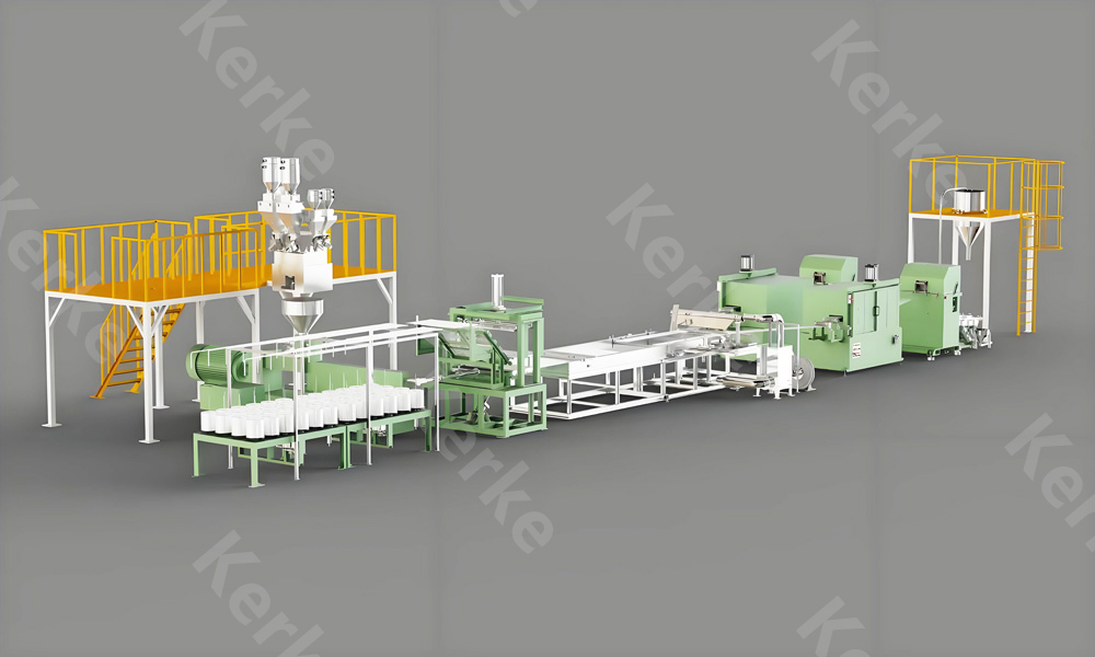
Introduction to Production Line Setup
Installing a new twin screw extruder production line is a complex engineering project that requires careful planning, precision execution, and thorough testing. Whether you are setting up a masterbatch line, a compounding plant, or a recycling facility, the success of your operation depends on a correct setup. A poorly installed line can lead to chronic downtime, quality inconsistencies, and safety hazards. This comprehensive guide walks you through every phase of the setup process, from site preparation to the first successful run, incorporating best practices recommended by Kerke Extruder for our global client base.
Phase 1: Site Preparation and Foundation
Before the machinery arrives, the physical site must be prepared. Twin screw extruders are heavy and generate significant vibration. The floor must be level and capable of supporting the concentrated weight of the extruder, gearbox, and downstream equipment. We recommend a reinforced concrete foundation with a minimum depth depending on the machine size. For large Kerke extruders (e.g., 95mm or 120mm), a mass concrete block foundation isolated from the main building floor is often necessary to dampen vibration. Additionally, ensure adequate space around the machine for maintenance access, operator movement, and raw material storage. The ceiling height must accommodate the length of the extruder plus the vertical space required for the pelletizing system or die head.
Phase 2: Utilities and Infrastructure
A twin screw line requires several utilities. The most critical is electricity. These machines have high power demands, often requiring 380V/400V/415V (depending on region) 3-phase power, and for large lines, medium voltage (10kV). The electrical cabinet must be supplied with the correct voltage and amperage, and proper grounding is essential for safety and signal stability. Next is cooling water. The barrel, gearbox, and melt pump (if equipped) require chilled water. The water temperature and pressure must be stable; fluctuations can cause process instability. Industrial chillers are usually required. Compressed air is needed for pneumatic actuators and hopper loading. Finally, consider ventilation. Compounding processes release fumes and VOCs; a local exhaust system over the feed throat and vent ports is necessary to maintain a safe working environment.
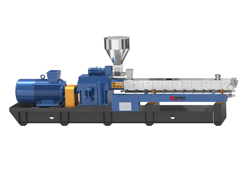
Phase 3: Machine Unloading and Rigging
When the Kerke extruder arrives, it will be shipped in sections (barrel, gearbox, motor, control panel). Use heavy-duty cranes and forklifts for unloading. Never drag the machine components. The barrel sections are precision machined and can be easily damaged if bumped. Store the components in a clean, dry area. If assembly is delayed, apply rust preventative to machined surfaces. The screws and barrel liners should be stored vertically or on supports to prevent warping. Follow the rigging diagram provided in the manual explicitly to avoid tipping the heavy gearbox or motor.
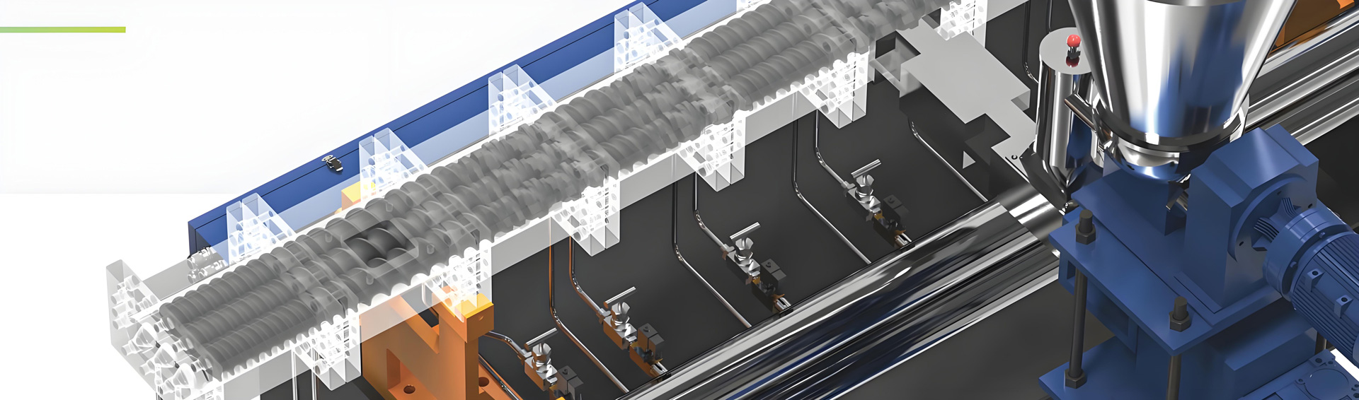
Phase 4: Mechanical Assembly and Alignment
Assembly begins with mounting the gearbox to the base frame. Level the gearbox using shims; this is the reference point for the entire machine. Once the gearbox is leveled, the barrel sections are bolted onto the gearbox output flange. It is crucial to torque the bolts in the correct sequence and to the specified values to ensure a leak-tight seal. The motor is then mounted to the input side of the gearbox. The key step here is the alignment of the motor coupling to the gearbox input shaft. Laser alignment tools are highly recommended to ensure the shafts are perfectly collinear, which prevents vibration and bearing failure. Finally, the screws are inserted into the barrel. This must be done carefully to avoid damaging the flight surfaces. The screws are connected to the gearbox output shafts using splined couplings or clamp rings.
Phase 5: Electrical and Control Wiring
With the mechanical assembly complete, the electrical team connects the power cables, heater bands, thermocouples, and control sensors. All heater bands should be checked for continuity before installation to ensure there are no short circuits. The thermocouples (usually J or K type) must be inserted into the barrel pockets with thermal paste to ensure good heat transfer. The control cabinet is wired to the main power supply. Kerke extruders use advanced PLC control systems (Siemens or equivalent). The wiring must be shielded to prevent electromagnetic interference (EMI) from the high-power motors affecting the sensitive sensor signals. The emergency stop circuits and safety interlocks (door sensors, overload relays) must be tested rigorously before powering up the heaters.
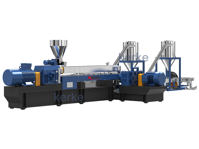
Phase 6: Auxiliary Equipment Installation
The extruder is just one part of the line. Auxiliary equipment must be installed and synchronized. This includes the feed system (hopper, loss-in-weight feeders), liquid injection systems (for additives or coupling agents), the vacuum system (for devolatilization), the screen changer (hydraulic or continuous), and the pelletizing system (strand cutter or die face cutter). The feeders must be mounted rigidly to the extruder throat. The vacuum pump needs to be placed as close as possible to the vent port to minimize pressure drop. The pelletizer must be aligned with the die face. All these devices need to be integrated into the central control PLC so they start and stop in the correct sequence. Kerke provides communication protocols (Profibus, Profinet, Modbus) to ensure seamless integration of all peripheral devices.
Phase 7: Commissioning and Heating Up
Commissioning starts with a “cold check.” With the machine off, verify all wiring, check screw rotation direction (it must be co-rotating), and ensure all moving parts turn freely. Then, engage the heaters. Set the barrel zones to the process temperature. It is critical to ramp up the temperature slowly (e.g., 20-30 degrees per hour) to prevent thermal shock to the barrel and screws. Once the setpoints are reached, hold the temperature for at least 2 hours to allow the metal to stabilize thermally (soak). This ensures the barrel expands evenly. Check all heater bands for proper function using an ammeter to verify they are drawing current.
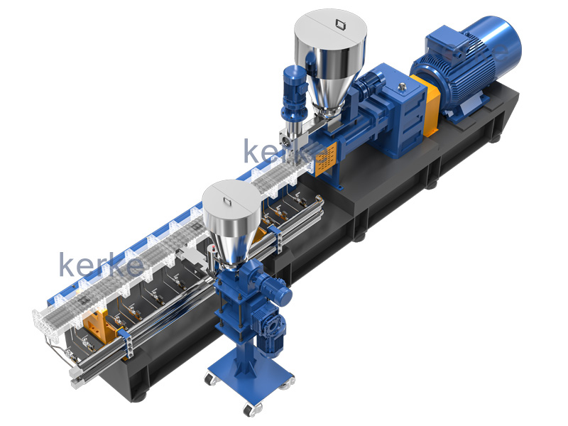
Phase 8: Screw Configuration and Start-Up
Before introducing material, ensure the screws are configured correctly for the intended product. For masterbatch, this usually means a high percentage of kneading blocks in the mixing section. Verify the clearance between the screws and the barrel. Start the drive motor at a very low speed (e.g., 5-10 RPM). Listen for any unusual noises—grinding or knocking indicates a mechanical issue. Check the rotation direction again. Gradually increase the speed while monitoring amperage (torque) and head pressure. If the machine has a vacuum vent, start the vacuum pump only after the melt has filled the vent zone to prevent material from being sucked into the pump. Introduce the feed material slowly, starting with regrind or carrier resin before adding pigments or fillers.
Phase 9: Process Tuning and Optimization
Once the machine is running, the tuning process begins. Adjust the feed rate, screw speed, and barrel temperatures to achieve the target melt temperature and pressure. Use the lab results to guide you. If the dispersion is poor, you may need to increase the temperature or screw speed (shear). If the material is degrading, reduce the temperature or increase the feed rate to reduce residence time. Record all parameters in the recipe management system. Kerke control systems allow you to save hundreds of recipes, making it easy to switch between different products. Optimization also involves the downstream equipment—adjusting the haul-off speed and cutter speed to get the correct pellet size and shape.
Phase 10: Safety Checks and Operator Training
Safety is paramount. Before full production, conduct a comprehensive safety audit. Ensure all guards are in place, emergency stops are functional, and fire suppression systems are active. Operators must be trained on the specific hazards of the extruder: hot surfaces, moving parts, electrical hazards, and the risk of melt pressure release (die head explosion). Kerke engineers provide on-site training covering normal operation, startup, shutdown, and emergency procedures. Training should also cover lock-out/tag-out (LOTO) procedures for maintenance. Only trained personnel should be allowed to operate the line.
Phase 11: Maintenance Schedule and Spare Parts
A new line requires a proactive maintenance schedule. This includes daily checks (oil levels, leak checks, sensor functionality), weekly greasing of bearings, and monthly inspection of screws and barrels for wear. Keep a stock of critical spare parts: heater bands, thermocouples, seals, and wear elements. Kerke Extruder maintains a warehouse of spare parts and can ship them globally within 24-48 hours to minimize downtime. Implement a predictive maintenance program using vibration analysis on the gearbox and motor to detect issues before they cause a breakdown.
Phase 12: Quality Control and Validation
The final phase is validating that the production line meets quality standards. Take samples of the compounded material at regular intervals. Test for properties like Melt Flow Index (MFI), color consistency (using a spectrophotometer), dispersion (using a filter pressure test or microscopy), and mechanical properties. Compare these results against your specifications.100% and the lab trials. If there are deviations, fine-tune the process parameters. Document the validated process as the “Golden Batch” recipe. This rigorous validation ensures that when you scale up to 24/7 production, the quality remains consistent.
Conclusion
Setting up a new twin screw extruder production line is a significant investment of capital and resources. However, by following this structured guide—paying attention to foundation preparation, precise alignment, utility infrastructure, and thorough commissioning—you can ensure a smooth start-up and rapid return on investment. Kerke Extruder is not just a machine supplier; we are your partner in this journey, providing technical support from the initial site visit to the final quality validation. With a properly set up Kerke twin screw line, you will have a robust, efficient, and high-quality production capability that will serve your business for decades.