Screw configuration represents one of the most consequential decisions in twin screw extrusion processing. The arrangement of screw elements along the drive shaft determines material flow patterns, mixing intensity, residence time, and ultimately the quality of finished masterbatch product. An optimized screw configuration delivers superior dispersion, efficient production, and consistent quality batch after batch. Understanding the principles underlying screw configuration selection enables processors to maximize the performance potential of their compounding extruders.
The complexity of screw configuration optimization may seem daunting to those new to twin screw extrusion. Hundreds of screw element types and thousands of possible configurations create vast possibility space. However, systematic understanding of fundamental principles enables logical selection of configurations suited to specific applications. This comprehensive guide walks through the technical considerations, configuration strategies, and practical guidance that support effective screw configuration decisions for masterbatch production.
Fundamental Principles of Twin Screw Extruder Design
Understanding twin screw extruder fundamentals provides essential context for screw configuration decisions. The interaction between screw elements, barrel geometry, and material characteristics determines processing outcomes. This foundational knowledge supports logical configuration selection rather than reliance on trial and error.
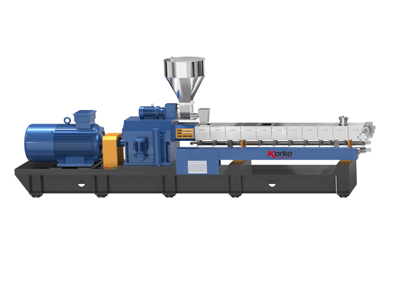
Co-Rotating Intermeshing Screw Principles
Co-rotating twin screw extruders feature two screws that rotate in the same direction while their flights intermesh. This intermeshing geometry creates positive displacement material flow that systematically advances material through the barrel. Material is trapped between screw flights and barrel surfaces, then transported forward as screws rotate. The intermeshing zone provides an important mixing function as material passes between screws.
The flight geometry of screw elements determines their material transport capability. Standard conveying elements feature flights that push material forward efficiently. Reverse flight elements create material backflow that increases residence time and mixing. The clearance between screw flights and barrel surface affects transport efficiency and mixing intensity. Understanding these geometric fundamentals enables appreciation of how different element types affect processing.
The Role of Shear in Compounding Processes
Shear stress applied to material during extrusion performs critical functions in masterbatch production. Shear breaks apart pigment agglomerates, dispersing individual pigment particles throughout the carrier matrix. Shear also promotes mixing by creating velocity gradients that relative displace material layers. Sufficient shear intensity and duration ensures complete pigment dispersion that produces consistent color in finished products.
Shear rate depends on screw speed, screw geometry, and barrel geometry. Higher screw speeds increase shear rates throughout the processing volume. Closer clearance between screws and barrel increases shear rates locally. Kneading blocks create particularly high shear due to their disk geometry and arrangement. Understanding how configuration decisions affect shear enables processors to ensure adequate dispersion without excessive degradation of heat-sensitive materials.
Residence Time and Its Importance
Material residence time within the extruder significantly impacts processing outcomes. All material must receive sufficient exposure to processing conditions to achieve intended results. However, excessive residence time may degrade heat-sensitive components or reduce production efficiency. Optimal residence time depends on formulation requirements and production objectives.
Screw configuration directly controls material residence time through its influence on material flow patterns. Forward conveying elements promote rapid transport that reduces residence time. Reverse elements and kneading blocks create material restriction that increases residence time. Fill level within the barrel also affects residence time distribution. Configuration optimization balances these factors to achieve appropriate total exposure for each formulation.
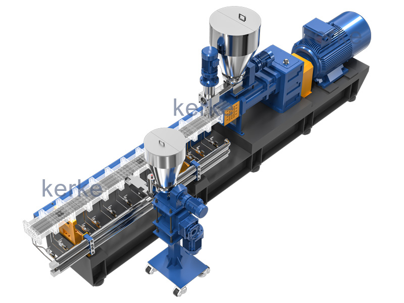
Understanding Screw Element Types and Functions
Twin screw extruders employ diverse screw element types, each serving specific functional purposes. Familiarity with these element types enables intelligent configuration decisions that address specific processing requirements.
Conveying Elements for Material Transport
Conveying elements form the backbone of screw configurations, providing primary material transport through the barrel. These elements feature helical flights that push material forward as screws rotate. Standard pitch conveying elements provide moderate transport efficiency suitable for general purpose applications. Wide pitch elements increase output capacity at the cost of reduced fill level control. Narrow pitch elements provide greater fill control for processing sensitive formulations.
Conveying element length and arrangement determines basic material flow characteristics. Longer conveying sections in the feed zone facilitate material introduction and feeding. Transition sections between different element types require careful conveying element arrangement to maintain smooth material flow. Discharge sections typically use conveying elements optimized for smooth pressure development toward the die.
Kneading Blocks for Dispersive Mixing
Kneading blocks apply the intensive mixing required for pigment dispersion in masterbatch production. These elements consist of offset disk segments that create localized high-shear zones as screws rotate. Material experiences repeated compression and shearing as it passes through kneading block elements. The intensity and effectiveness of dispersive mixing depends on kneading block configuration.
Kneading blocks are available in various stagger angles that determine mixing intensity and transport behavior. Narrow stagger angles create more restrictive flow that increases mixing intensity and residence time. Wide stagger angles provide less restrictive transport with reduced mixing intensity. Multiple kneading blocks spaced along the screw create sequential mixing zones that progressively improve dispersion quality.
Mixing Disks for Distributive Mixing
Mixing disks provide distributive mixing that complements the dispersive mixing of kneading blocks. These elements feature narrow disks that create material folding and redistribution as screws rotate. Distributive mixing improves pigment distribution without the high shear that may damage sensitive materials. Combining kneading blocks and mixing disks creates comprehensive mixing that addresses both dispersion and distribution requirements.
Disk thickness influences mixing intensity and transport behavior. Thin disks provide gentle distributive mixing suitable for final blend homogenization. Thicker disks create more substantial flow restriction and increased residence time. Configuration of mixing disks should complement kneading block placement to achieve overall mixing objectives. The balance between dispersive and distributive mixing elements affects final product characteristics.
Specialized Elements for Specific Functions
Beyond basic conveying and mixing elements, specialized elements serve specific processing functions. Reverse pitch elements create material backflow that increases mixing intensity and residence time. These elements create restriction zones that concentrate processing in specific barrel regions. Specialty mixing elements incorporate geometric features designed for specific mixing objectives.
Some manufacturers offer proprietary element designs optimized for particular applications. These specialty elements may provide performance advantages for specific formulation types. However, compatibility with standard element geometries enables flexible configuration even with specialized elements. Understanding available element options expands the possibility space for configuration optimization.
Configuration Strategies for Masterbatch Applications
Masterbatch production presents specific processing requirements that influence screw configuration strategy. The concentration and dispersion of pigments demands particular attention to mixing capability. Carrier resin characteristics and additive requirements affect configuration decisions. Systematic approach to configuration development addresses these masterbatch-specific requirements.
Feed Zone Configuration Fundamentals
The feed zone accepts material introduction and initiates material transport through the extrusion system. Feed zone configuration significantly influences feeding behavior and throughput capacity. Wide pitch conveying elements facilitate material introduction from the hopper. Adequate feed zone length ensures smooth material flow into the compression zone.
Feed throat design and barrel barrel barrel barrel barrel barrel barrel barrel barrel barrel barrel barrel configuration interact with feed zone screw configuration. Adequate feed zone cooling prevents material bridging at the hopper. Overly restrictive feed zone elements restrict throughput capacity and cause feeding problems. Configuration optimization balances feeding efficiency against downstream compression and mixing requirements.
Compression Zone Design Considerations
The compression zone transitions material from loose granular or powder form to homogeneous melt. Proper compression zone design ensures complete melting without excessive shear that could degrade material. Transition from large pitch to smaller pitch conveying elements creates progressive compression that promotes melting. Adequate compression zone length prevents unmelted material from entering mixing sections.
Temperature profile and compression zone configuration interact to determine melting behavior. Higher barrel temperatures reduce viscosity and facilitate melting, potentially allowing shorter compression zones. Lower temperatures require longer compression zones or modified element arrangements to achieve complete melting. Configuration optimization should account for typical operating temperature ranges to ensure reliable melting across production conditions.
Mixing Section Optimization for Pigment Dispersion
The mixing section performs the critical pigment dispersion function that determines masterbatch color quality. Kneading blocks in this section provide dispersive mixing that breaks apart pigment agglomerates. The arrangement of kneading blocks along the screw creates sequential mixing that progressively improves dispersion. Multiple kneading blocks provide opportunity for repeated pigment exposure to high-shear zones.
Kneading block stagger angle affects both mixing intensity and pressure generation. Narrow stagger angles provide intense mixing but may create excessive pressure that affects throughput. Wider stagger angles reduce pressure generation while maintaining mixing capability. Some configurations use varying stagger angles through the mixing section to balance mixing intensity against pressure requirements. Disk thickness between kneading block disks also influences mixing behavior.
Discharge and Pumping Zone Configuration
The discharge zone converts mixing section output into pressure for extrusion through the die. Proper discharge zone configuration ensures smooth pressure development without disrupting the mixing achieved upstream. Conveying elements with moderate pitch provide efficient transport while building pressure toward the die. Final kneading or mixing elements immediately upstream of the die should be configured to avoid pressure disturbances.
Die pressure depends on throughput, viscosity, and die geometry. Higher die pressure improves melt homogeneity but increases mechanical stress on equipment. Configuration should support the pressure required for specific die designs while maintaining stable operation. Die adapter geometry also influences pressure requirements and should be considered when configuring the discharge zone.
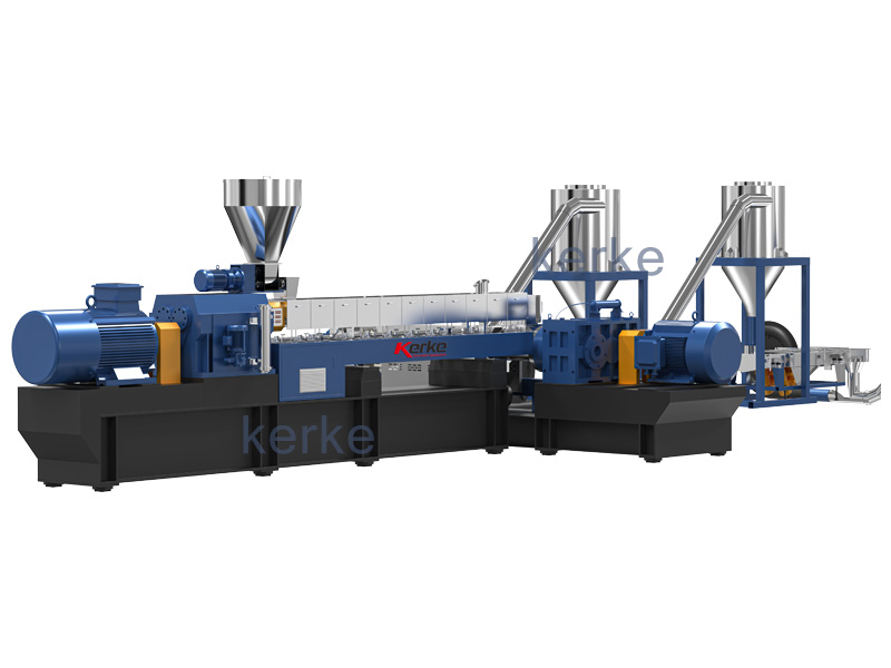
Matching Configuration to Kerke KTE Extruder Models
The Kerke KTE series includes extruder models suited to different production scales and requirements. Configuration optimization should account for the specific characteristics of each model to maximize performance.
KTE-36B Configuration Recommendations
The KTE-36B with 35.6mm screw diameter and 20 to 100 kg per hour capacity suits small batch and pilot production applications. Compact barrel volume enables rapid product changes and reduced material waste during setup. Configuration for this model should emphasize mixing quality over throughput, given its typical applications in development and specialty production. The $25,000 to $35,000 investment in this model should be leveraged through configurations optimized for flexibility.
KTE-36B configuration might include multiple kneading block zones with narrow stagger angles to maximize dispersion quality. Shorter barrel length relative to larger models requires efficient mixing section design. Configuration should ensure complete melting in limited barrel length. The compact model advantages include easy configuration changes that support experimentation with different formulations.
KTE-50B Configuration Guidelines
The KTE-50B with 50.5mm screw diameter and 80 to 200 kg per hour capacity addresses mid-scale production requirements. This model balances throughput capacity with processing flexibility suitable for diverse masterbatch formulations. The $40,000 to $60,000 investment supports professional production while maintaining configuration adaptability.
KTE-50B configuration can incorporate dedicated feed, compression, mixing, and discharge sections of appropriate proportions. Longer mixing sections compared to smaller models enable more thorough pigment dispersion. Multiple kneading block zones with varying stagger angles provide progressive mixing capability. Configuration should leverage the additional barrel length to achieve superior mixing without sacrificing throughput efficiency.
KTE-65B Production Optimization Configuration
The KTE-65B with 62.4mm screw diameter and 200 to 450 kg per hour capacity serves high-volume masterbatch production. Configuration for this model must balance mixing quality against throughput efficiency. The $50,000 to $80,000 investment supports substantial production capability that configuration optimization can maximize.
KTE-65B configuration benefits from longer dedicated mixing sections that improve dispersion without proportional throughput reduction. Wider barrel diameter affects shear characteristics compared to smaller models, requiring configuration adjustments for equivalent mixing. Multiple mixing zones with optimized kneading block arrangement achieve thorough dispersion at higher throughput rates. Configuration should account for production economics that favor throughput efficiency.
KTE-75B Industrial Production Configuration
The KTE-75B with 71mm screw diameter and 300 to 800 kg per hour capacity addresses industrial-scale production requirements. Configuration for this model emphasizes production efficiency while maintaining quality standards. The $70,000 to $100,000 investment supports demanding production environments where configuration optimization delivers significant value.
KTE-75B configuration requires careful attention to mixing section design given increased barrel diameter. Higher throughput rates require configuration that ensures adequate residence time for complete dispersion. Extended mixing sections or multiple kneading block zones may be necessary to achieve quality objectives. Configuration should leverage the model’s production capacity while meeting customer quality requirements.
KTE-95D Ultra-High Volume Configuration Strategy
The KTE-95D with 93mm screw diameter and 1000 to 2000 kg per hour capacity represents maximum production capability in the KTE series. Configuration for this model must maximize throughput efficiency while ensuring quality at scale. The $120,000 to $200,000 investment justifies substantial configuration optimization effort to maximize return.
KTE-95D configuration requires specialized attention to mixing efficiency given extreme throughput rates. Standard mixing section designs may prove insufficient at these production volumes. Extended mixing sections, additional mixing zones, or specialized high-intensity mixing elements may be necessary. Configuration should be developed through systematic testing that verifies quality achievement at target throughput rates. Production economics at this scale create strong incentives for configuration optimization.
Process Parameters and Configuration Interaction
Screw configuration interacts significantly with process parameters to determine final processing outcomes. Understanding these interactions enables integrated optimization that configuration alone cannot achieve. Parameter settings should complement configuration design to achieve optimal results.
Screw Speed Optimization Considerations
Screw speed affects multiple processing characteristics including shear rate, residence time, and throughput. Higher screw speeds increase shear rates throughout the barrel, intensifying mixing but potentially degrading heat-sensitive materials. Higher speeds also reduce residence time by accelerating material transport. Configuration and screw speed interact to determine overall processing intensity.
Optimal screw speed depends on formulation characteristics and production objectives. High-viscosity formulations may require reduced speeds to maintain acceptable motor load. Low-viscosity formulations may accommodate speed increases without motor overload. Configuration with intensive mixing elements may require reduced speed to prevent excessive shear. Systematic speed studies identify optimal operating ranges for specific configurations and formulations.
Temperature Profile Development for Specific Configurations
Temperature profile significantly affects material viscosity, melting behavior, and processing stability. Configuration influences optimal temperature profile by determining residence time and mixing intensity in different barrel zones. Higher temperatures reduce viscosity, potentially allowing reduced motor load and improved mixing. However, excessive temperatures may degrade heat-sensitive materials.
Configuration with intensive mixing elements may require reduced temperatures to compensate for increased shear heating. Configuration with limited mixing capability may require elevated temperatures to achieve equivalent processing. Barrel zone temperatures should be optimized through systematic studies that correlate temperature settings with product quality. Configuration and temperature profile development should proceed together for optimal results.
Throughput and Fill Level Considerations
Throughput directly affects material fill level within the barrel and residence time distribution. Higher throughput increases fill level and reduces residence time. Lower throughput decreases fill level and increases residence time. Configuration affects how throughput influences these parameters through its impact on transport efficiency and mixing intensity.
Fill level significantly affects mixing efficiency and temperature development. Low fill levels reduce mixing efficiency by decreasing material compaction. High fill levels may exceed mixing capability, resulting in inadequate dispersion. Configuration should maintain appropriate fill levels across the intended throughput range. Operating procedures should account for the interaction between configuration and throughput.
Configuration Optimization Methodology
Systematic configuration optimization ensures that screw designs support production objectives effectively. Testing and refinement based on documented results enables continuous improvement in configuration performance.
Starting Configuration Selection Guidelines
Initial configuration selection should balance proven designs with application-specific customization. Manufacturer recommendations provide starting points based on general experience. Literature references for similar applications offer additional starting configuration options. Selection should consider formulation characteristics, production requirements, and equipment specifications.
Standard configurations available from equipment suppliers provide tested starting points for optimization. These configurations typically address general-purpose applications effectively. Application-specific modifications based on formulation characteristics improve upon standard starting points. Documentation of starting configurations and modification rationale supports systematic optimization.
Systematic Testing and Refinement Process
Configuration optimization requires systematic testing that isolates the effects of specific changes. Documentation of test conditions, parameters, and results enables meaningful comparison between configurations. Testing should vary one parameter at a time when possible to clearly identify effects of specific changes. Product quality testing including dispersion evaluation and color measurement provides objective performance assessment.
Refinement should proceed from major configuration decisions toward fine-tuning details. Initial testing should address major functional zones before optimizing specific element arrangements. Once major configuration decisions are validated, incremental refinements can address fine details. Configuration optimization represents ongoing process improvement rather than one-time exercise.
Documentation and Knowledge Management
Configuration documentation preserves optimization results and supports future reference. Documentation should include complete element specifications, arrangement drawings, and rationale for major decisions. Configuration performance data should be recorded for each formulation tested. Lessons learned during optimization inform future configuration development efforts.
Knowledge management systems capture configuration expertise for organizational benefit. New personnel can access documented knowledge rather than starting from scratch. Configuration libraries enable reuse of validated designs for similar applications. Investment in documentation and knowledge management multiplies the value of configuration optimization efforts.
Common Configuration Mistakes and How to Avoid Them
Configuration errors can compromise processing quality and equipment performance. Awareness of common mistakes helps processors avoid pitfalls that degrade results.
Insufficient Mixing Section Design
Inadequate mixing section length or intensity represents the most common configuration mistake affecting masterbatch quality. Pigment agglomerates that escape dispersion create color variation and quality problems in finished products. Configuration should ensure that mixing capability matches dispersion requirements for the specific pigment systems and concentrations being processed.
Assessment of mixing section adequacy should include product testing at normal production rates. Quality problems appearing only at high throughput may indicate insufficient mixing section for that production rate. Additional kneading blocks or modified stagger angles often resolve insufficient mixing problems. Configuration should be validated across the intended production range, not just at nominal operating conditions.
Excessive Restriction Causing Pressure Problems
Configuration with excessive restriction creates pressure problems that affect throughput and equipment stress. Back pressure from restrictive elements increases motor load and may trigger overload shutdowns. Pressure variations create instability that affects product quality. Configuration should balance mixing intensity against pressure generation limits.
Pressure monitoring during configuration testing identifies excessive restriction problems. Motor load monitoring provides additional indication of restriction problems. Reducing kneading block stagger angles or removing restrictive elements resolves pressure problems. Configuration should be tested across intended operating ranges to ensure stability under all expected conditions.
Feeding and Melting Zone Configuration Errors
Inadequate feeding zone design causes throughput limitations and feeding instability. Poor compression zone design results in unmelted material entering mixing sections. These problems degrade product quality and cause equipment stress. Configuration should ensure reliable feeding and complete melting across intended operating ranges.
Feed zone configuration should accommodate material characteristics including bulk density, flow properties, and melting behavior. Compression zone length should match melting requirements for the carrier resin and operating temperatures used. Testing with actual production materials identifies feeding and melting problems early in configuration development. Modification of feed and compression zone configuration resolves most problems in these functional zones.
Future Trends in Screw Configuration Technology
Screw configuration technology continues to evolve with new element designs, computational tools, and understanding of mixing processes. Staying informed about developments supports continued improvement in configuration practice.
Computational Modeling and Simulation Advances
Computational fluid dynamics and finite element analysis increasingly support configuration development. These tools enable prediction of flow patterns, shear distribution, and temperature development for proposed configurations. Simulation reduces trial-and-error experimentation that consumes time and materials. However, simulation requires validation against physical testing to ensure accuracy.
Machine learning algorithms show promise for configuration optimization based on accumulated testing data. These approaches can identify patterns that inform configuration decisions for new formulations. Integration of simulation, testing, and learning systems enables continuous improvement in configuration practice. Investment in computational tools supports more efficient configuration optimization.
Advanced Element Designs and Materials
New screw element designs continue to emerge from research and development efforts. These designs may offer improved mixing efficiency, reduced wear, or enhanced functionality for specific applications. Advanced materials including wear-resistant coatings extend element service life in demanding applications. Specialty materials may enable processing of previously challenging formulations.
Configuration practices should evolve as new element options become available. Testing of new elements against current standards determines whether adoption improves performance. Economic analysis balances potential performance improvements against costs of new element acquisition. Configuration optimization remains an ongoing activity as technology advances.
Conclusion
Screw configuration selection fundamentally determines processing capability in twin screw extrusion for masterbatch production. Understanding screw element types and their functions enables logical configuration decisions. Configuration strategy addresses the specific requirements of feed zones, compression zones, mixing sections, and discharge zones. Matching configuration to specific KTE extruder models maximizes equipment performance across the product range.
The Kerke KTE series from compact KTE-36B models at $25,000 to $35,000 through ultra-high volume KTE-95D systems at $120,000 to $200,000 benefits from thoughtful configuration selection. Configuration optimization should account for production scale, formulation requirements, and quality objectives. Systematic testing and documentation enable continuous improvement in configuration practice. Masterbatch manufacturers that invest in configuration expertise achieve superior quality and production efficiency that supports business success.